| Music Gear Repair and Hacking /\ | ||
|
Check out my YouTube channel. |
|
|
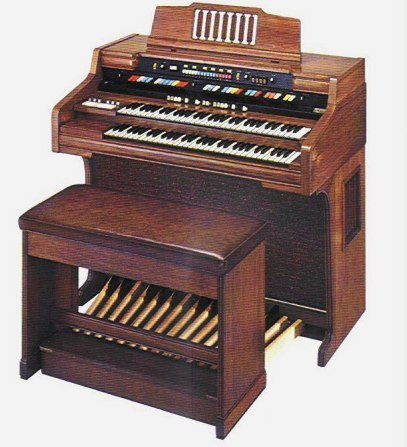
I got this organ really cheap in the fall of 2009. It is solid state, but does a pretty good imitation of an older tonewheel organ like a B3. It has a little built-in Leslie speaker and all kinds of weird gadgets like an analog drum machine (which sounds a little like a TR-808), Symphonic Strings (which sound kind of like a Roland VP-330's strings), automatic chording, Fascinating Fingers II (an arpeggiator), etc.
I decided to add a MIDI Out interface to it so I could use it to control the Miditzer software. (Try the Miditzer...it's free and fun to play with!)
|
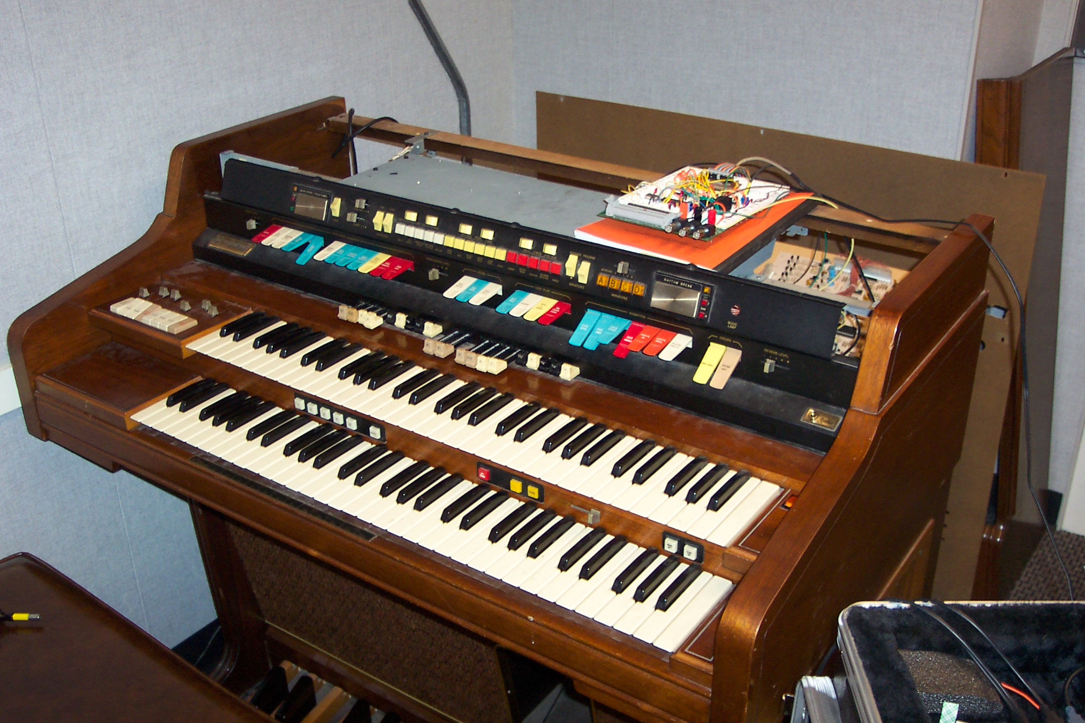
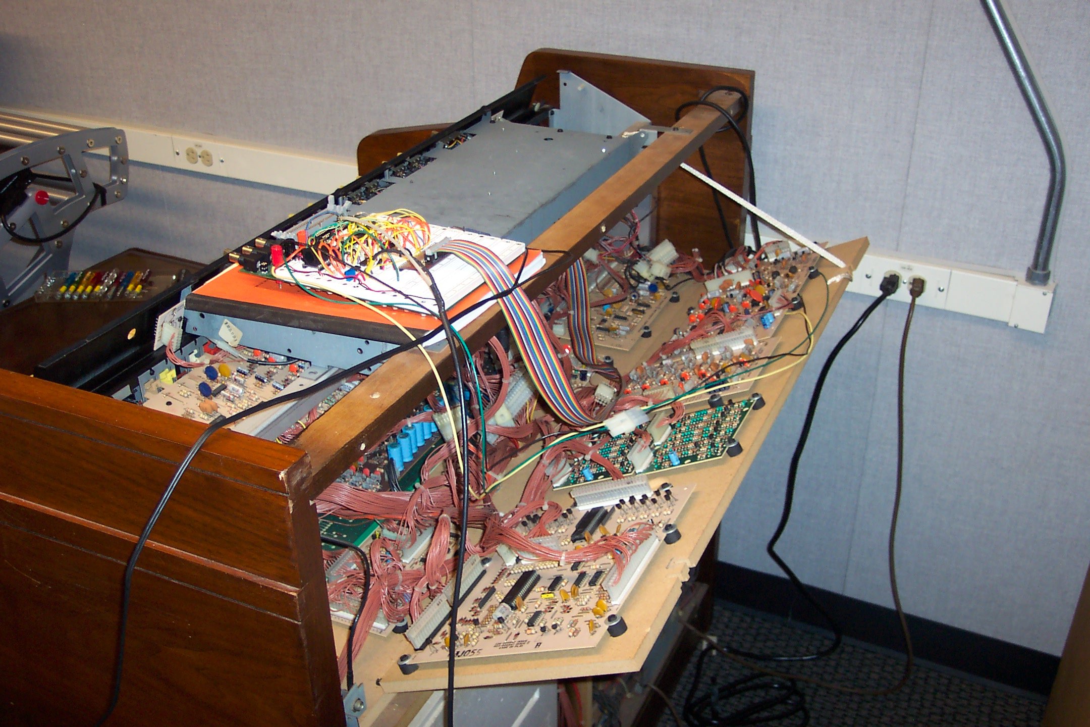
I am designing the boards myself and programming a PIC 16F877 chip to generate the MIDI. The key contacts on the Commodore output about -20V when the key is pressed. I wanted to use CD4067 16-to-1 analog multiplexer chips, which cannot handle a voltage range wider than about 20 volts, to scan the keys into the PIC. So I am using voltage dividers to reduce each key signal to about -2V before it goes through the multiplexers. The multiplexer chips are running on +/- 5V power supplies generated by 7805 and 7905 voltage regulators from the Commodore's +/- 24V supplies.
|
Here is what it sounds like when the organ is driving a synth in Reaktor: (1.4 MB mp3). The Hammond is doing the drawbar sound, strings, arpeggiator (sorry, FASCINATING FINGERS II), and drum machine. Reaktor is being driven by the top manual and is doing the analog-synth-like notes.
(Click on a link to see a page about that part of the system)
   ┌─────────────┐          ┌────────┐
   │             │X1      X4│ Upper  │X1  Ribbon
   │             │<────────>│  Man   │<───────────
   │             │          │  Mux   │X2  Ribbon    Wires soldered
   │             │          │ Board  │<───────────  onto key boards
   │             │          │        │X3  Ribbon
   │             │          │        │<───────────
   │             │          └────────┘
   │             │
   │             │          ┌────────┐
   │             │X2      X4│ Lower  │X1  Ribbon
   │             │<────────>│  Man   │<───────────
   │             │          │  Mux   │X2  Ribbon    Wires soldered
   │             │          │ Board  │<───────────  onto key boards
   │             │          │        │X3  Ribbon
   │             │          │        │<───────────
   │             │          └────────┘
   │             │
   │             │          ┌────────┐
   │             │X3      X4│ Pedal  │
   │             │<────────>│  Mux   │
   │             │          │ Board  │X1 Ribbon     Wires soldered
   │             │          │        │<───────────  onto terminals
   │             │          │        │              on 'Ease of
   │             │          │        │              Play' board
   │             │          └────────┘
   │             │
   │             │          ┌────────┐
   │             │X4      X5│ Upper  │X1    X1┌───────────────────┐
   │             │<────────>│ Manual │<──────>│ Long Button Board │
   │             │          │        │        └───────────────────┘
   │             │          │  2nd   │
   │             │          │ Touch  │X2    X1┌───────────────────┐
   │             │          │ Master │<──────>│ Long Button Board │
   │             │          │  Mux   │        └───────────────────┘
   │             │          │ Board  │
   │             │          │        │X3    X1┌───────────────────┐
   │             │          │        │<──────>│ Long Button Board │
   │             │          │        │        └───────────────────┘
   │             │          │        │
   │    Main     │          │        │X4    X1┌────────────────────┐
   │    PIC      │          │        │<──────>│ Short Button Board │
   │    Board    │          └────────┘        └────────────────────┘
   │             │
   │             │          ┌────────┐
   │             │X5      X5│ Lower  │X1    X1┌───────────────────┐
   │             │<────────>│ Manual │<──────>│ Long Button Board │
   │             │          │        │        └───────────────────┘
   │             │          │  2nd   │
   │             │          │ Touch  │X2    X1┌───────────────────┐
   │             │          │ Master │<──────>│ Long Button Board │
   │             │          │  Mux   │        └───────────────────┘
   │             │          │ Board  │
   │             │          │        │X3    X1┌───────────────────┐
   │             │          │        │<───────│ Long Button Board │
   │             │          │        │        └───────────────────┘
   │             │          │        │
   │             │          │        │X4    X1┌────────────────────┐
   │             │          │        │<──────>│ Short Button Board │
   │             │          └────────┘        └────────────────────┘
   │             │
   │             │          ┌────────┐
   │             │X6      X1│ Left   │
   │             │<────────>│ Stop   │
   │             │          │ Switch │
   │             │          │ Box    │
   │             │          └────────┘
   │             │
   │             │          ┌────────┐
   │             │X7      X1│ Right  │
   │             │<────────>│ Stop   │
   │             │          │ Switch │
   │             │          │ Box    │
   │             │          └────────┘
   │             │
   │             │          ┌────────┐
   │             │X8      X1│ Piston │
   │             │<────────>│ Mux    │
   │             │          │ Board? │
   │             │          │        │
   │             │          └────────┘
   └─────────────┘