| Hammond Commodore /\ | ||
|
Check out my YouTube channel. |
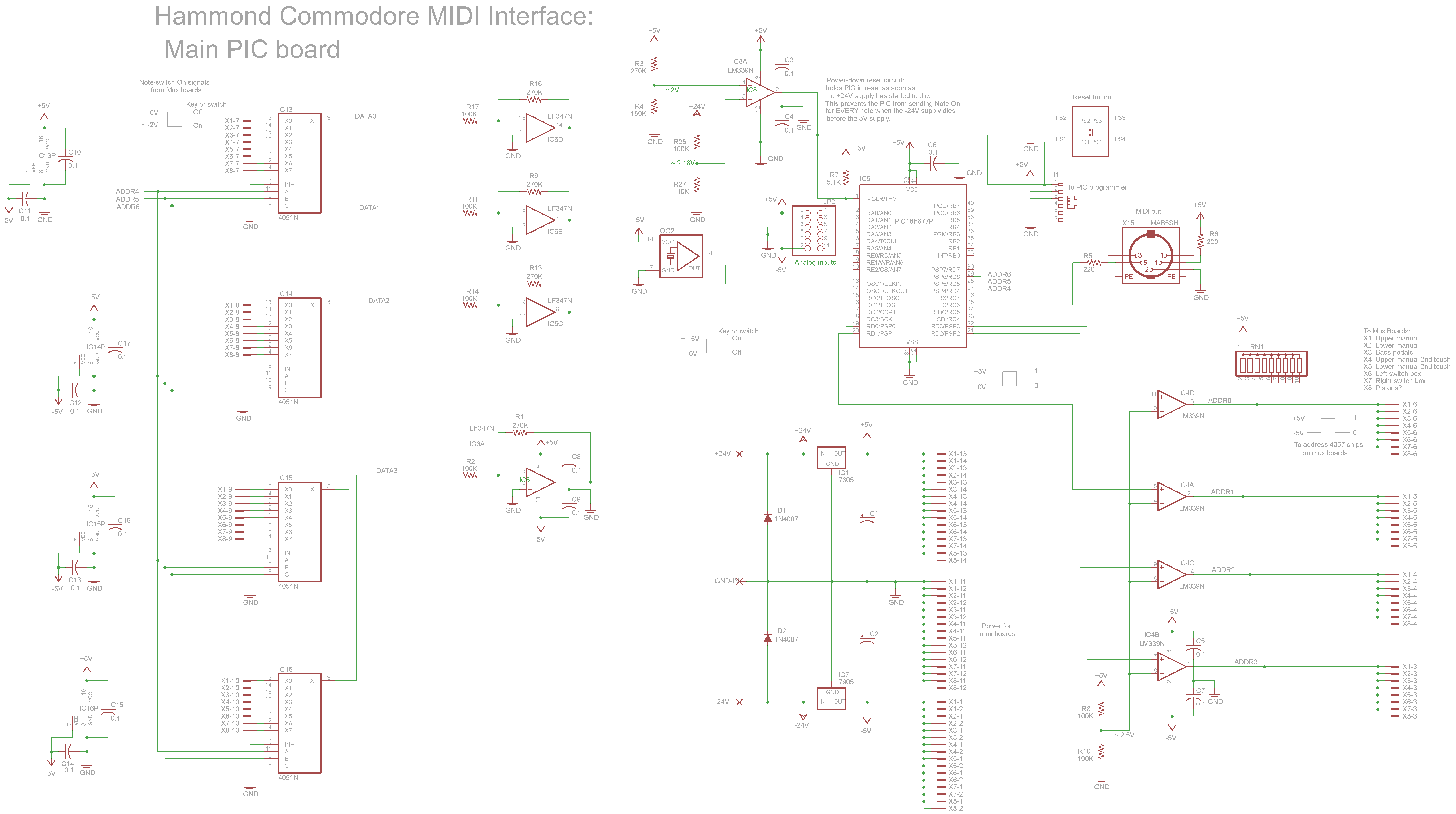
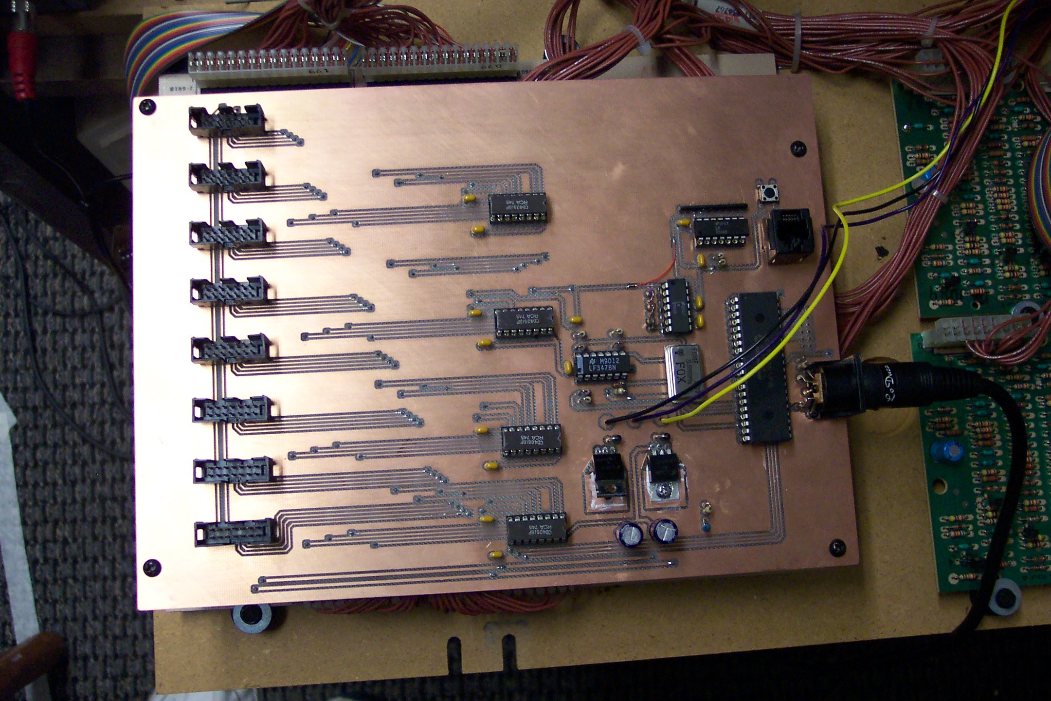
This board contains the PIC 16F877 processor and interface circuitry which scans the signals connected to the other boards.
The PIC outputs its logic signals at 0-5V. But I need to use it to send address bits to the analog multiplexer chips, which are running on +/- 5V power so they can pass the -2V key signals through. So I used LM339 comparator circuits to convert the PICs 0-5V signals into -5V-to-+5V signals before they go over the ribbon cables to control the CD4067 chips on the mux boards. Each PIC output is compared to 2.5V obtained from a simple voltage divider on the 5V supply.
The PIC also needs its logic inputs to swing between 0 and 5V. When the multiplexed key signals come from the manual mux boards, they are about -2V when the key is down and 0V when the key is up. So I use an inverting amplifier circuit on each key signal to turn it from -2V to about +4.3 volts before it goes to the PIC to be read. The boards from the sections other than the keyboards (bass pedals, switch boxes) are designed to output -2v signals so they will look just like manual mux boards to the PIC board.
When you power down the Commodore, its -24V power supply dies down to zero a long time before the +24V power dies, causing my -5V power to die long before my +5V power. When the -5V has died but the +5V is still on, my inverting amplifiers output +5V to the PIC constantly during multiple whole scans, making the PIC think that ALL the keys are down. So every time you switch the organ off, my interface sends out a MIDI Note On message for every single note! Whatever synth you are controlling with the MIDI generates a whole lot of stuck notes. Not pretty. So I added a circuit which detects when the +24 volt power has started to drop slightly after power is switched off (this fortunately happens before my -5V power has died) and grounds the reset line of the PIC, holding it in reset until the power dies out and preventing the spurious notes.
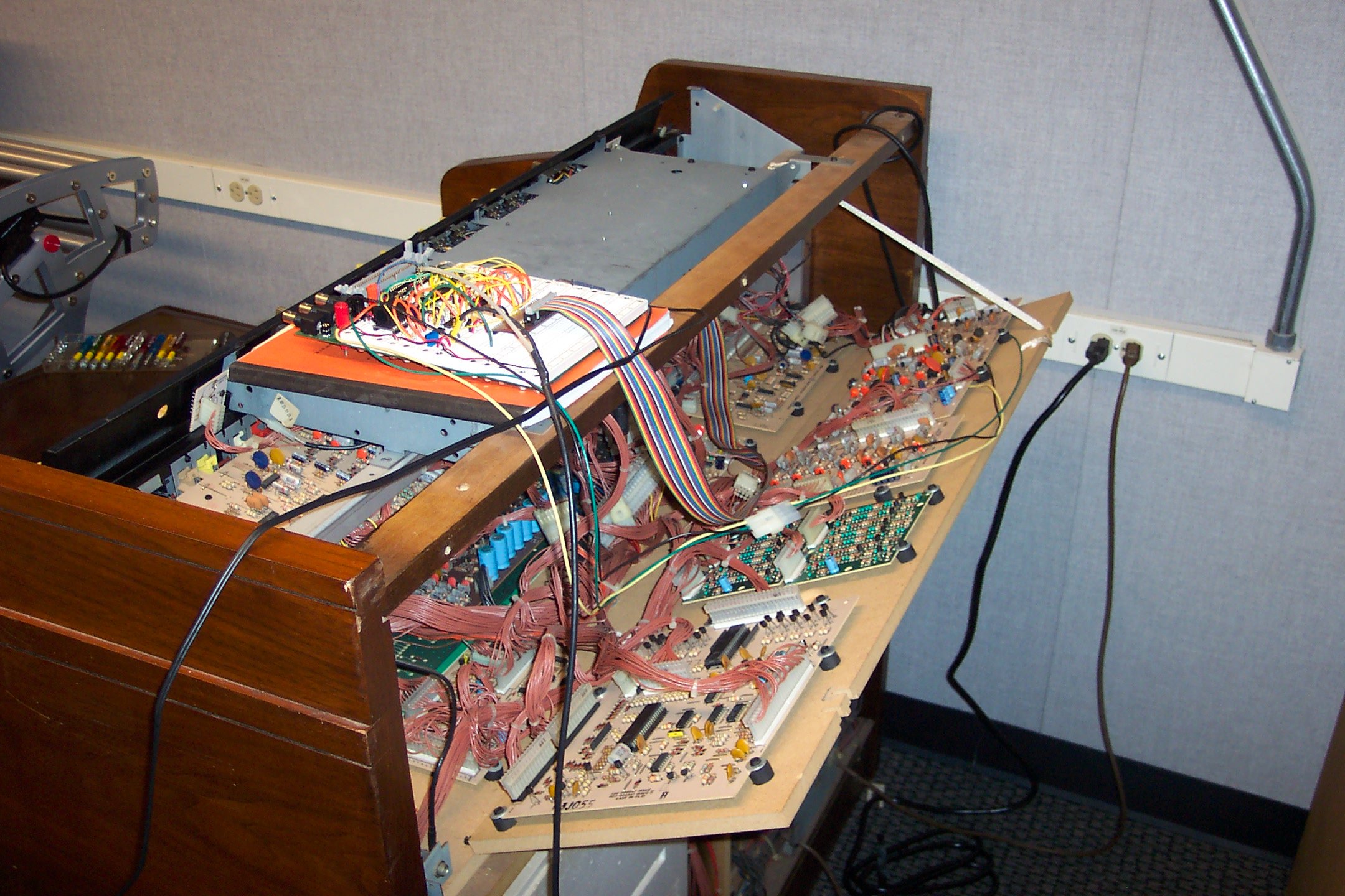
Here is the organ with the prototype master board sitting on top. The ribbon cable is coming from the manual Mux board mounted under the upper manual on the left side.
|
|
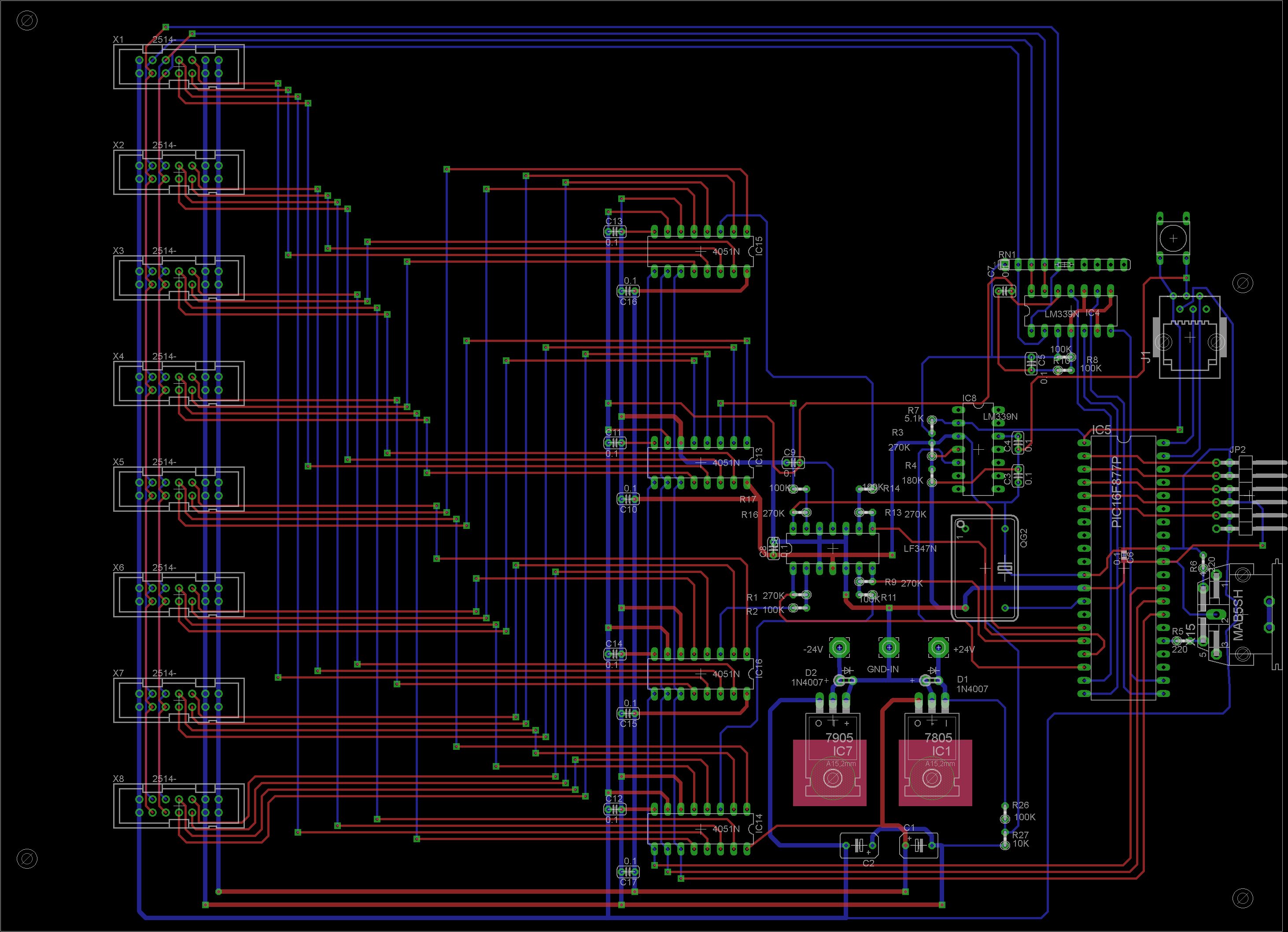
In late 2010 I redesigned the main board with an additional level of multiplexing, allowing the future addition of many more keys and stop switches. Here are the schematic and board layout of the permanent version, done with Eagle software.
|
|
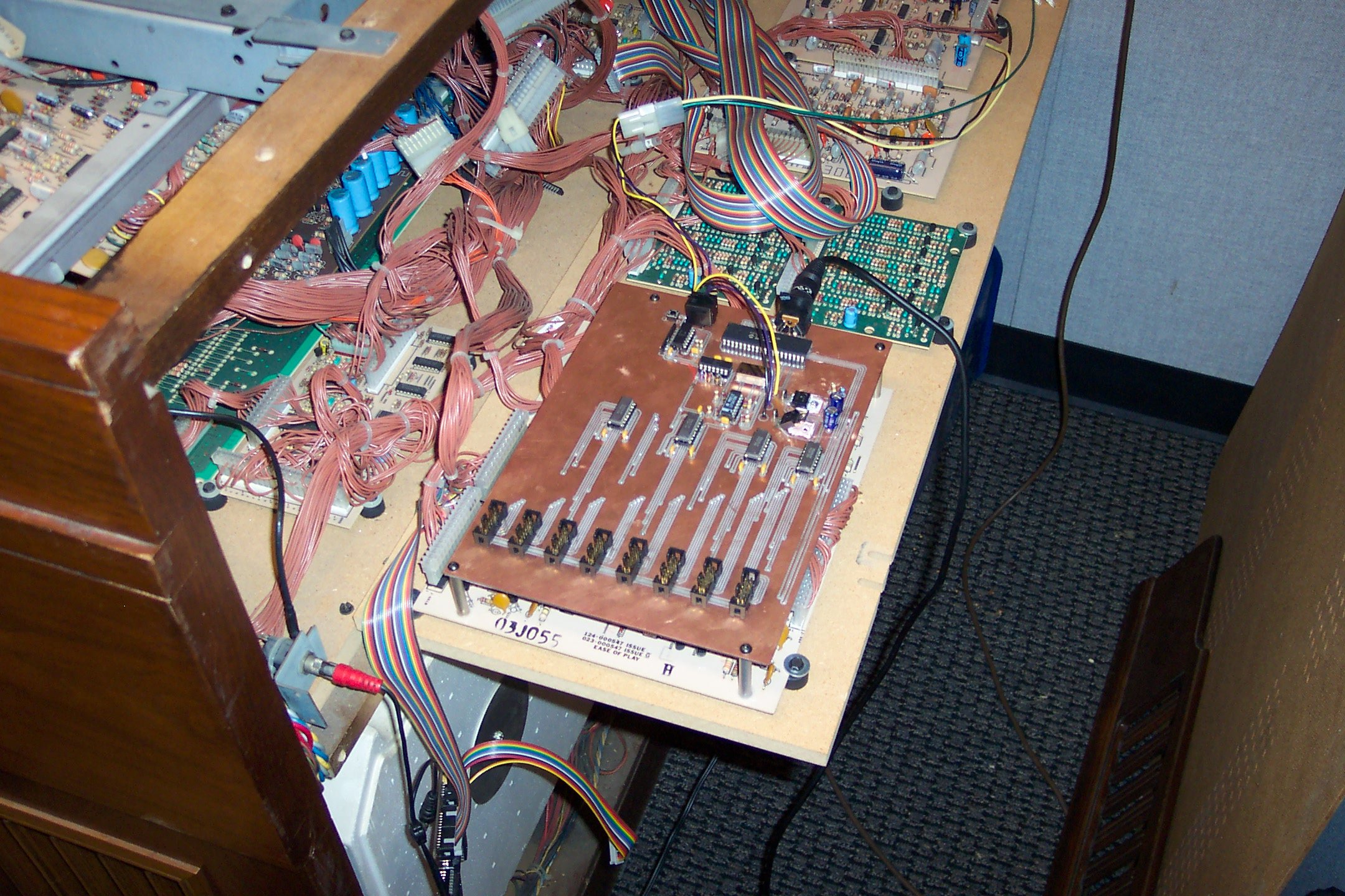
Here is a pic of the blank board before I soldered on the components.
Here is the finished board mounted on top of the Commodore's "Ease of Play" board.
|
|