The organ will have two switch boxes sitting on top allowing the player to switch different sections
on and off in the MIDItzer program the organ will be driving. I pasted LED strips on the
circuit board below so they shine through the paper and illuminate the labels.

|
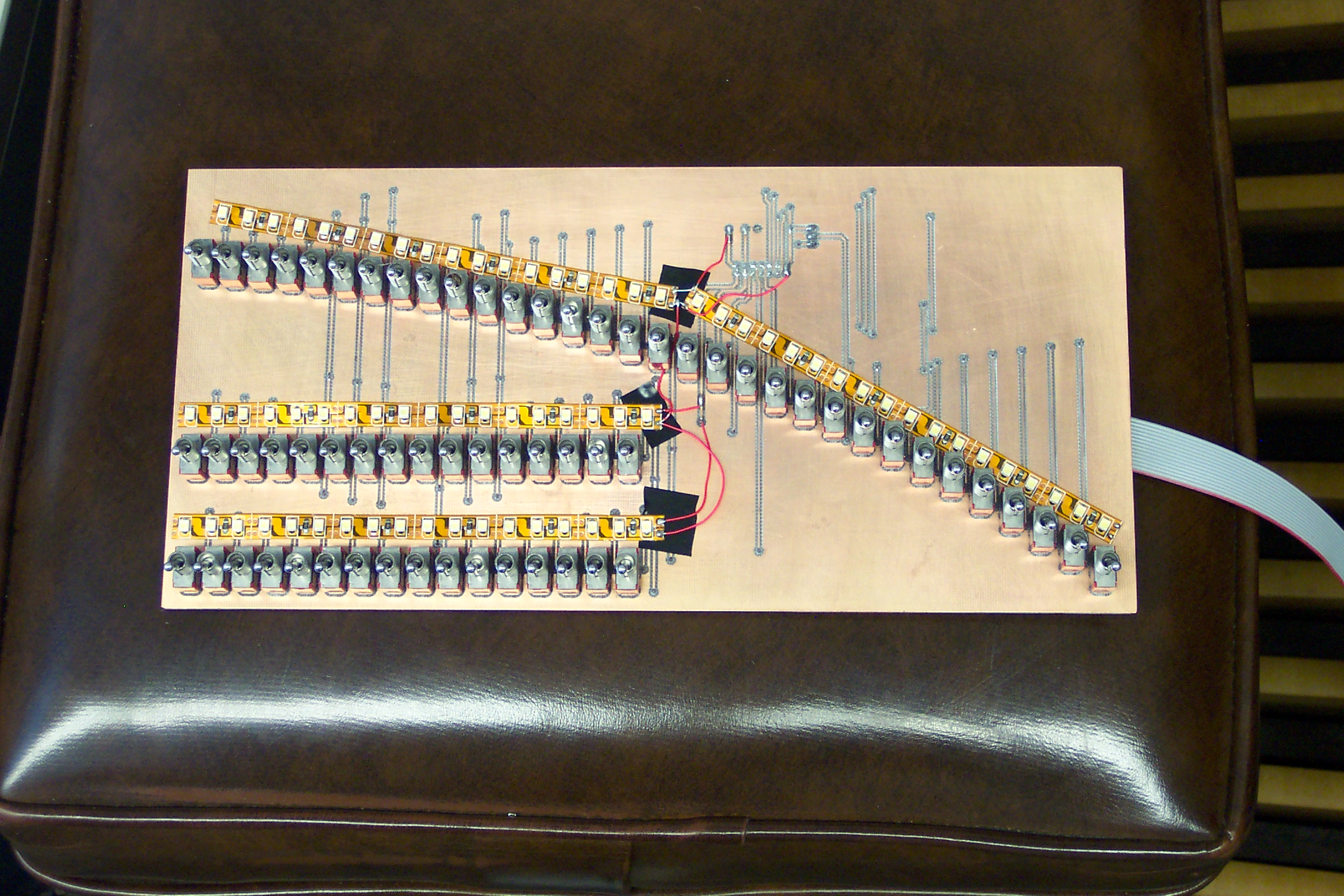
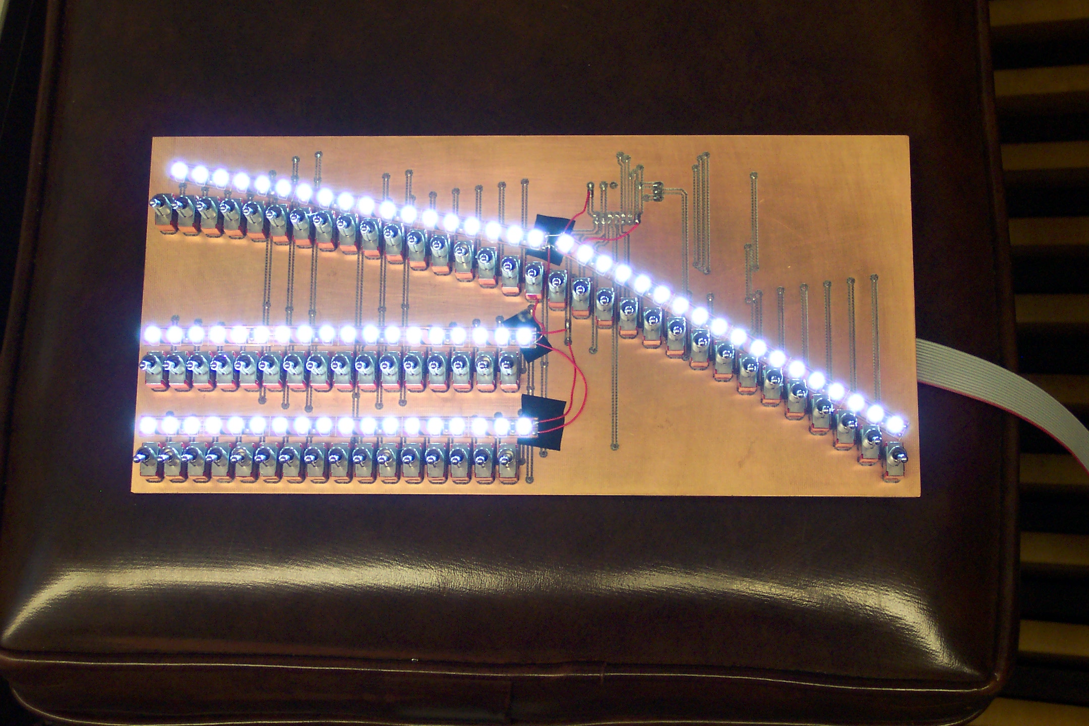
Here is the circuit board with all the PC-mount toggles switches. I pasted several LED strips
onto it which are powered from the +/- 5V supplies on the board.
|

|
Here is the circuit board with power applied.
|
|
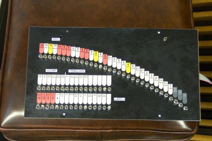
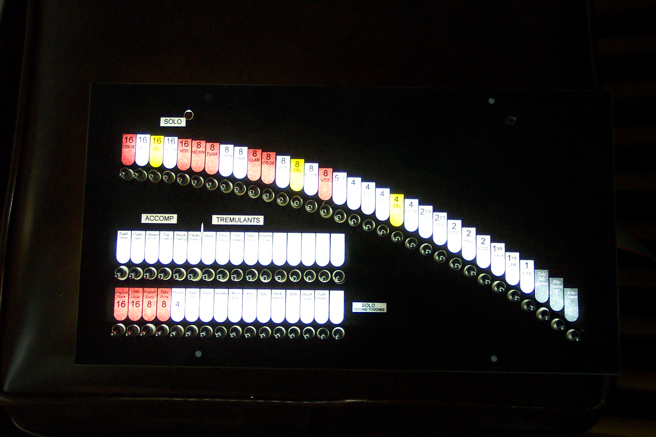
Here it is with the front panel on. The front panel is a piece of paper with
an inkjet print of the switch labels on a black background. I had this laminated and punched a lot of
holes in it with a leather hammer punch for the switches to stick through.
|

|
Here it is in the dark with the LEDs shining through the front panel.
|
