| Hammond Commodore /\ | ||
|
Check out my YouTube channel. |
|
|
|
|
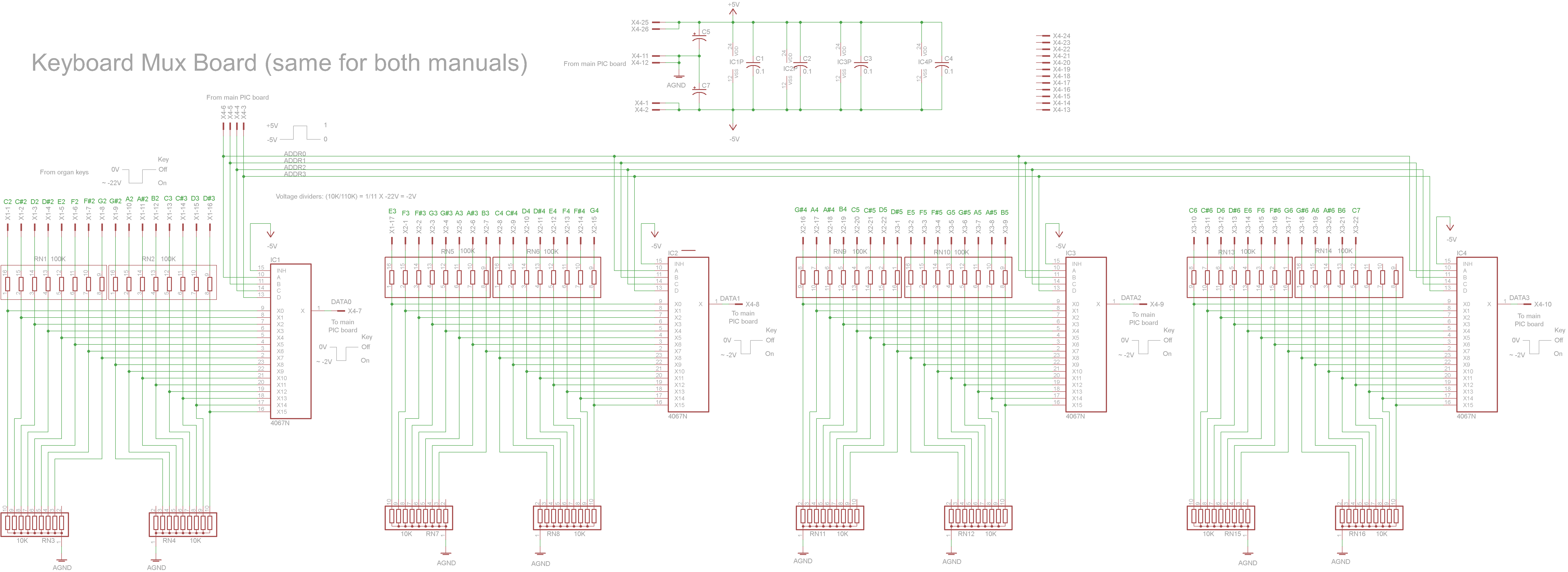
Each manual has one of these multiplexer boards mounted underneath and wired to all the keys on the manual. Each board contains 64 voltage dividers (only 61 are used currently, 1 for each key) to reduce the -20V key signals down to about -2V. They are then multiplexed down to 4 data lines using four CD4067 chips. A ribbon cable connects the Mux board to a central board with the PIC (currently a breadboard). It carries +5V, -5V, and ground pins to the Mux board as well as the 4 address lines to the multiplexers, and the 4 key voltage outputs from the multiplexers.
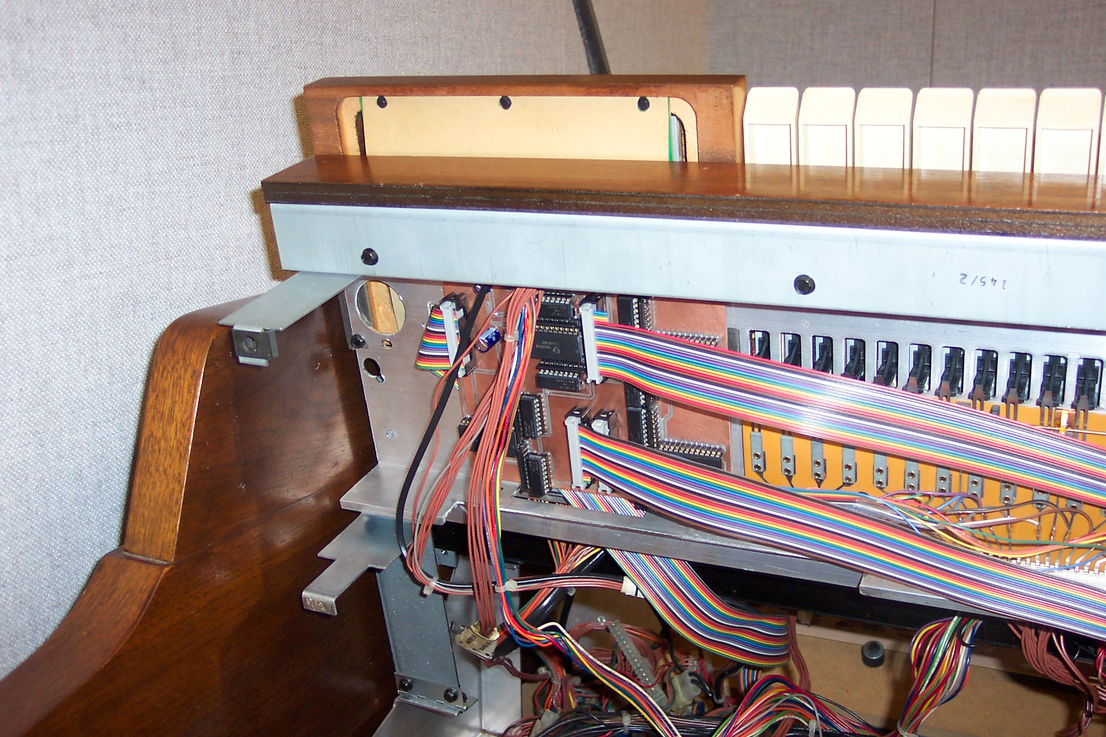
The Commodore conveniently has an empty circuit board mounting area on the left side under each manual. It appears that this is where the white-on-black drawbar preset keys board would go if the same frame hardware was used on a higher-end Hammond from the same era, like the Concorde. This was the perfect place to mount my multiplexer board on each manual.
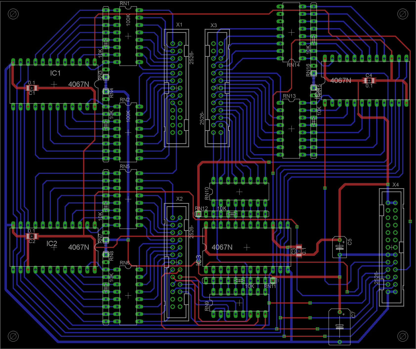
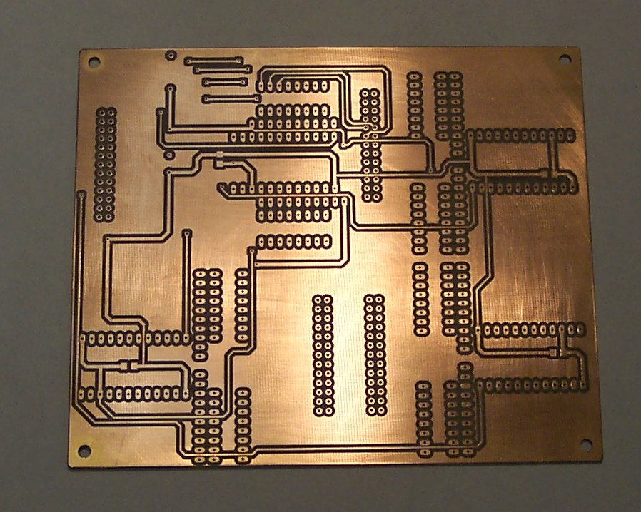
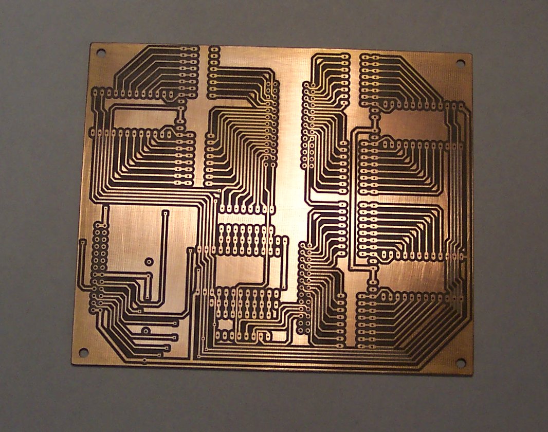
I designed the boards using Eagle and used an LPKF milling machine to fabricate them. Here is the second Mux board before adding the parts.
|
|
Here is what the Mux board looks like installed to the left of the upper manual. I originally wanted to use screws and spacers to hold the board in, but it proved so difficult to reach the area with a drill that I resorted to sticking it on with double-stick tape.
|
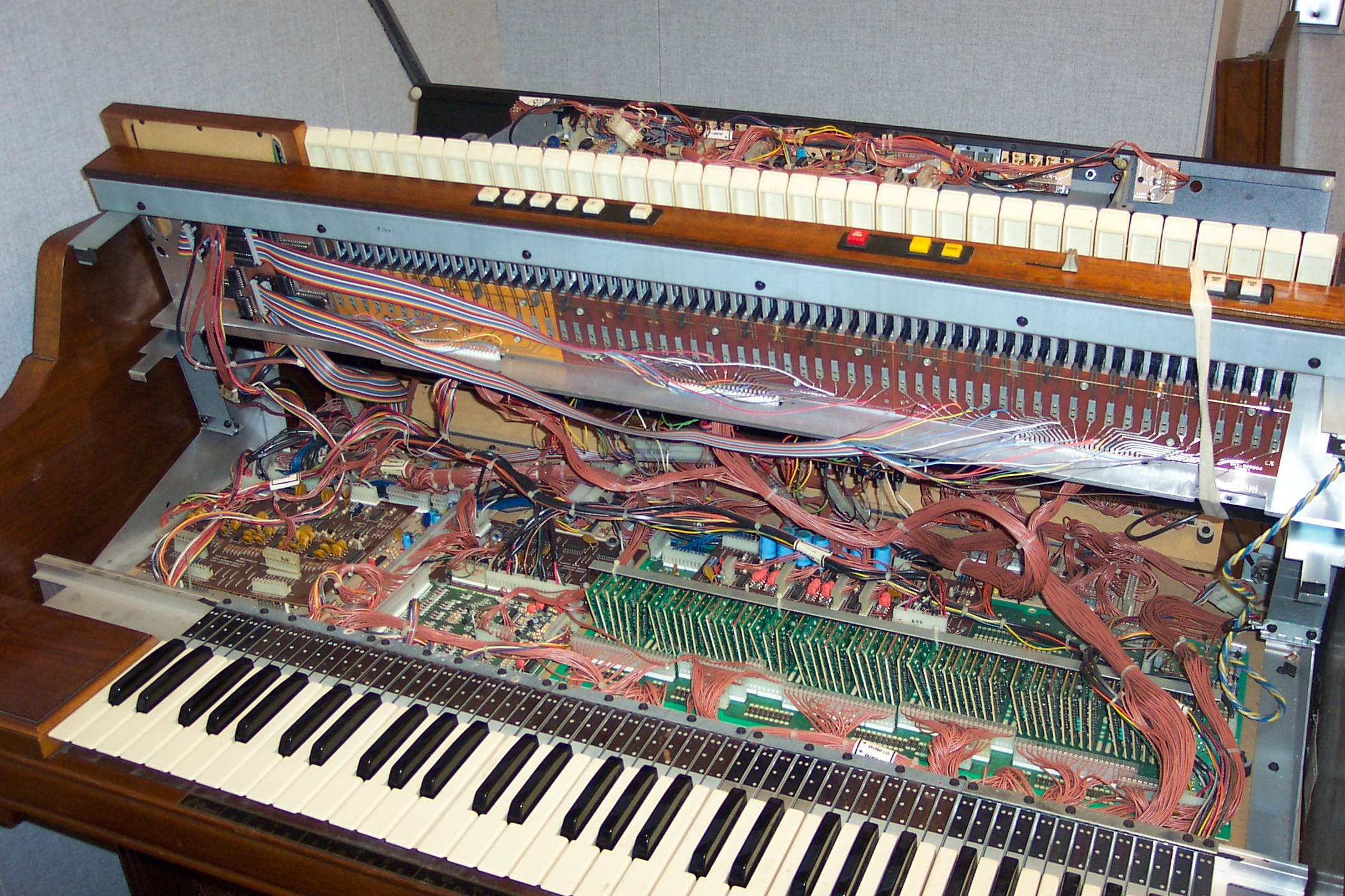
Since the key signals are mounted on 3 separate boards within the Commodore, I soldered a separate ribbon cable to each one so the boards can still be removed separately. The ribbon cables run to three 26-pin connectors on the Mux board. I intend to tie the wiring down a little more neatly.
|
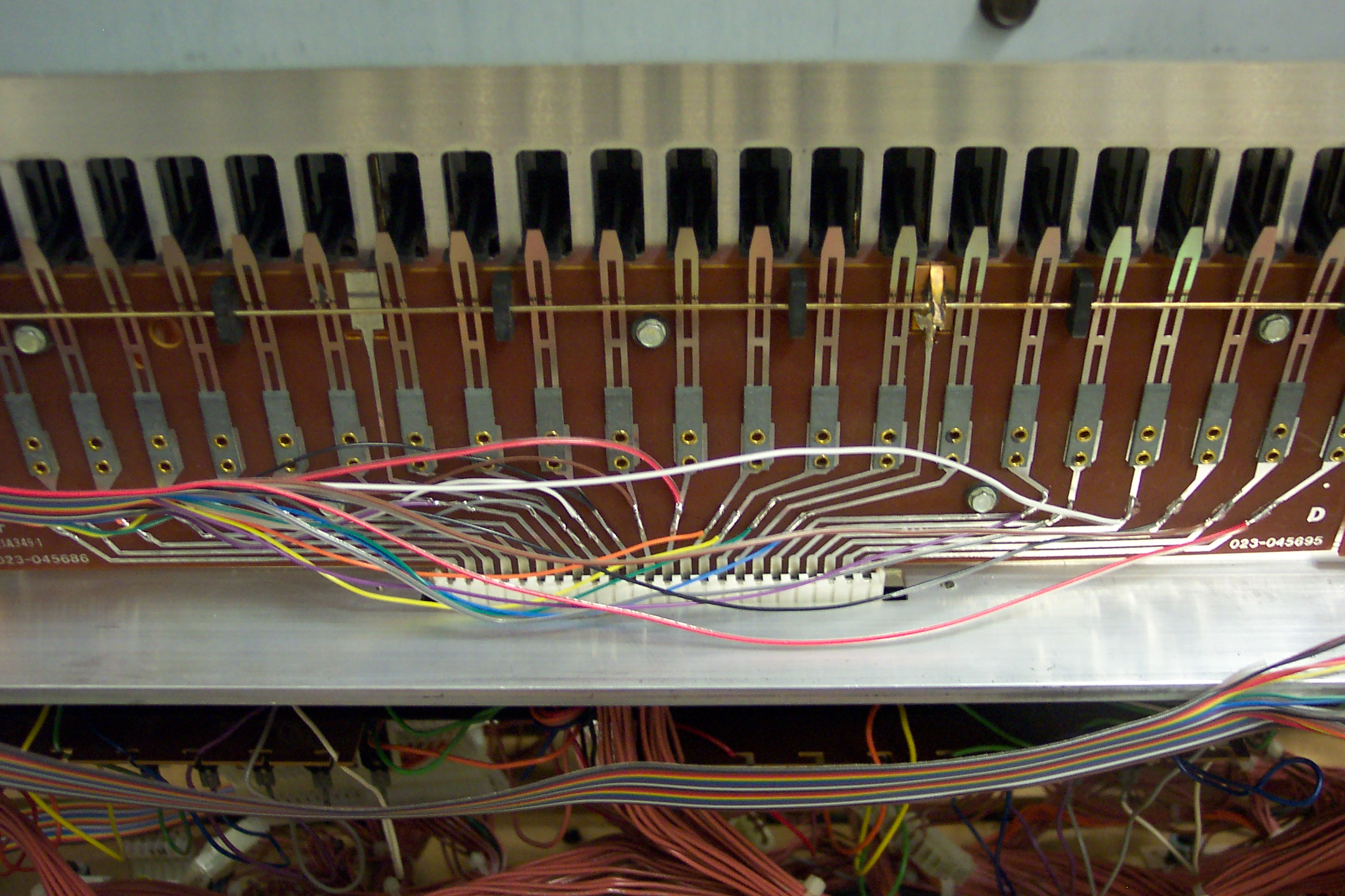 This picture shows how the individual wires from the ribbon cables are soldered onto the traces of the key boards. |