James Beauchamp Harmonic Tone Generator Exhibit

|
|
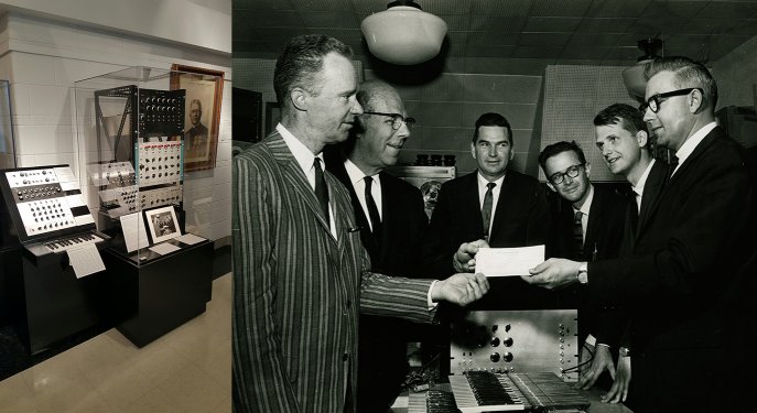
Left to right: Duane Branigan, Director of the School of Music; William Everitt,
Dean of the College of Engineering; James T. Smith, director of Urbana Government Operations
for the Magnavox Company; Prof. L. A. Hiller of the School of Music; James Beauchamp, graduate
student conducting research under Hiller's direction; and George A. Schupp, director of
engineering for Magnavox.
|
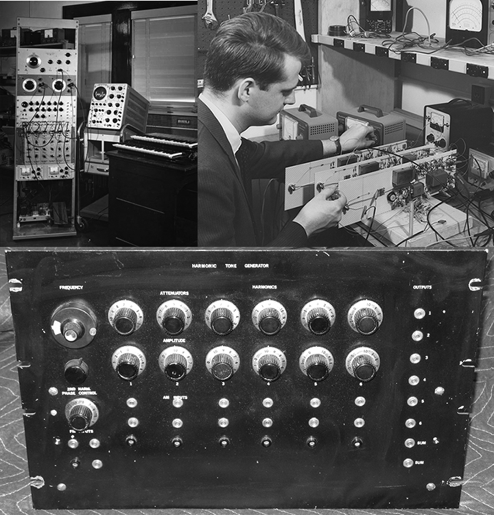
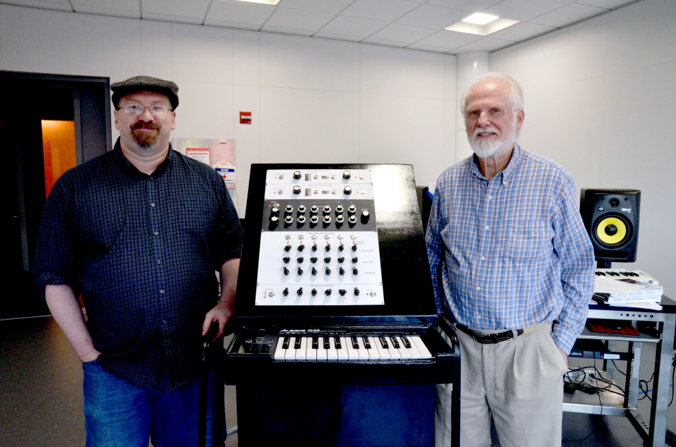
In the early 1960s, Dr. James Beauchamp from the University of Illinois developed
the Harmonic Tone Generator, an additive synthesizer that allowed the
user to build up a sound from 6 sine waves precisely tuned to the harmonic series. At the time, this
was very difficult to do electronically, and Beauchamp figured out how to do it by heterodyning signals up to
ultrasonic frequency (like in an AM radio). Another interesting thing about it was that each harmonic had a separate
envelope to control its loudness over time, and the user could add a delay time between when the note was played and when the
sine wave started its envelope. This allowed for interesting timbre changes that were not possible on
other synthesizers at the time.
Sousa Archives Exhibit
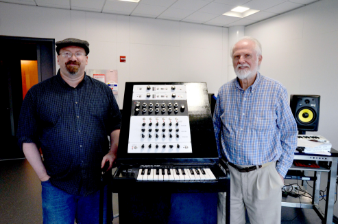
In 2015, Jim donated the original hardware to the
Sousa Archives at the University of Illinois. It no longer works and
would be very difficult to repair because of the unavailability of parts. I worked with Jim and Scott Schwartz from
the Sousa museum to build an emulator that could be played by museum visitors to show how the original worked. It is now housed
at the museum.
Here is an article about the project on the ECE Illinois page.
The emulator consisted of a laptop computer running Native Instruments' Reaktor software, connected via USB to an
Alesis Q25 mini keyboard
and a Livid Brain 2 MIDI board. These were mounted
inside a wood cabinet constructed by Sousa Archives Director Scott Schwartz.
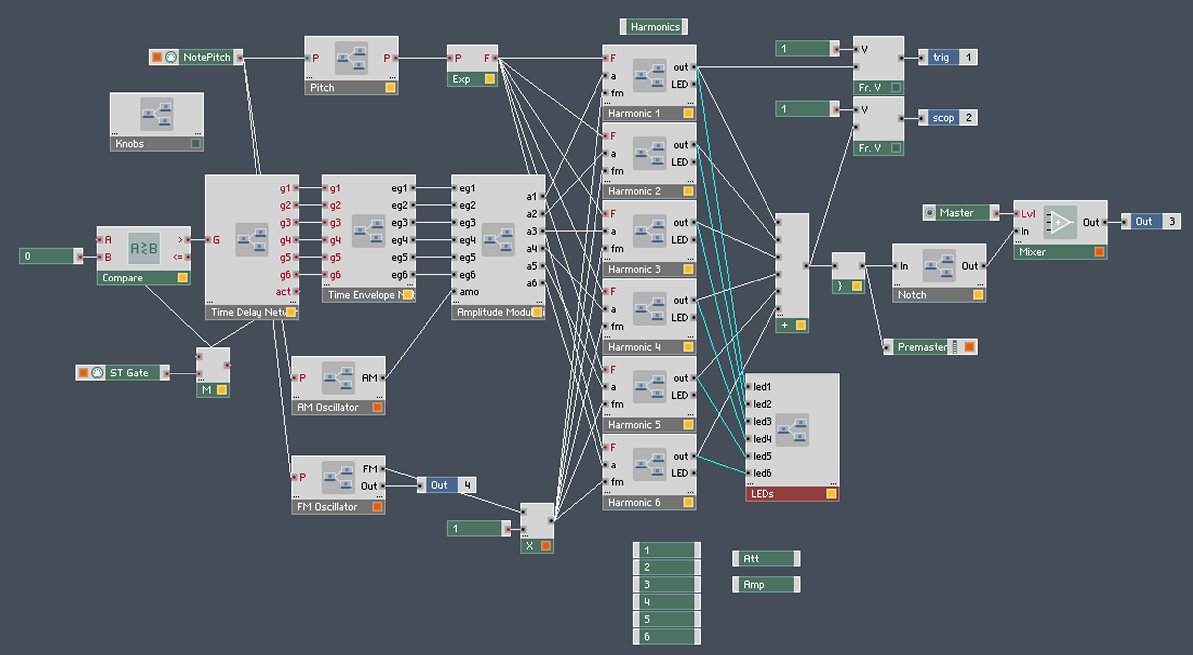
Custom Reaktor Ensemble
Here are images of the panel and structure of the Reaktor ensemble I designed.
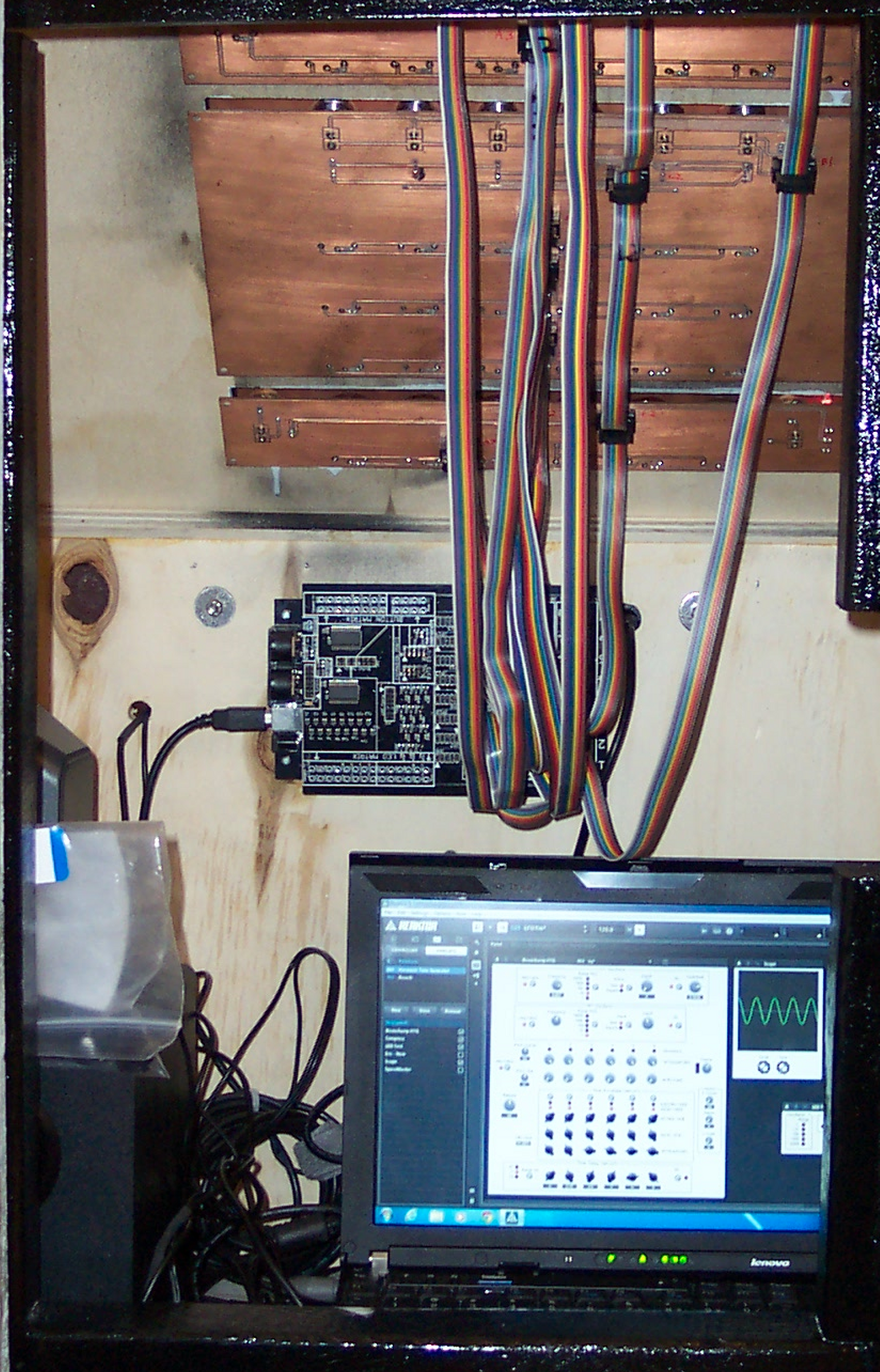
Circuit Boards
For each panel in the
(slightly reduced) rack, I designed one circuit board to connect the pots, buttons, and LEDs to the brain board
and another board to serve as a front panel. The inner circuit boards connect to the headers on the Brain board with ribbon cables.
Here is the inside of the cabinet from the back with the door open:
The Brain scans the buttons and pots and sends MIDI data (Continuous Controller messages) to
Reaktor when the controls are moved. Then Reaktor sends MIDI back to the brain board to tell it when to turn the LEDs on and off.
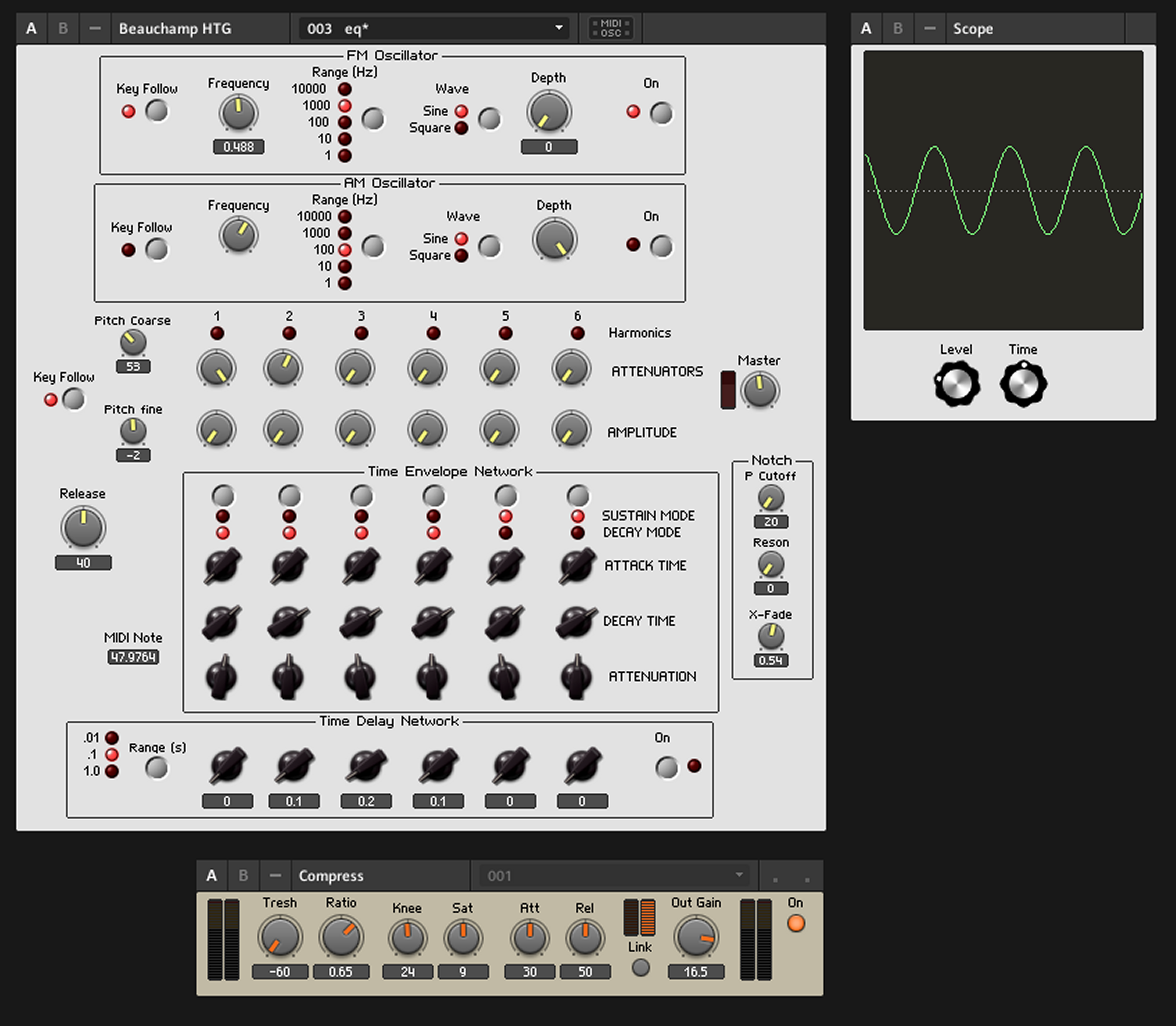
Front Panel
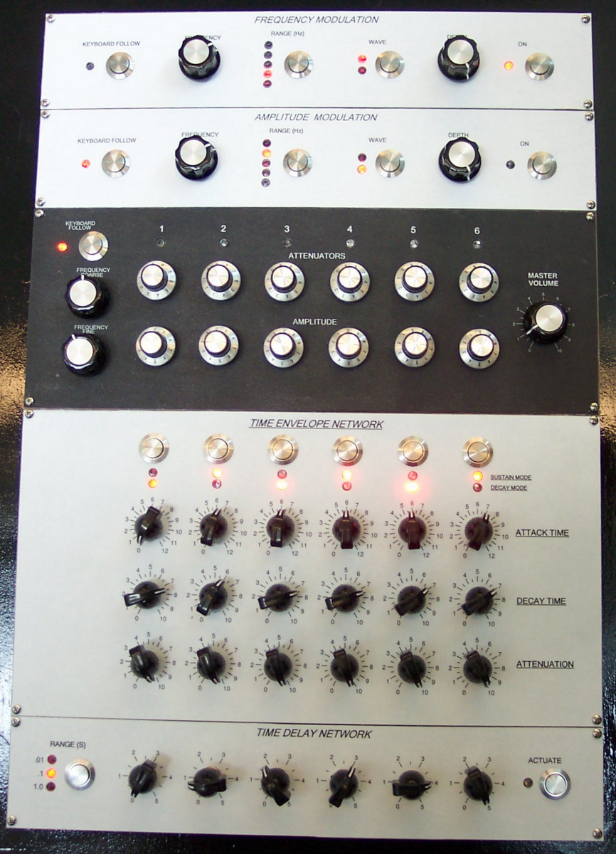
Here is a shot of the complete front panel
|
 <--- FM Modulation Oscillator


 <--- AM Modulation Oscillator


 <--- Harmonics Panel


 <--- Time Envelope Panel


 <--- Time Delay Panel
|
In order to make the HTG more child-proof, the slide switches on the original have been replaced
by pushbuttons which toggle LEDs to indicate the present state.
Talk and Demonstration at the Museum
On November 11th, 2015 Jim and I gave a talk at the Sousa Archives about the project.
Here is a page about it
posted by Skot Wiedmann.
WILL Radio Story
Illinois Public Media did an article and radio story about the project.
.
Video Demonstrations
Scott Schwartz from the Sousa archives created this demo video
of the HTG Emulator in action.
A video of me demonstrating the unit.