| Analog Modifications /\ | ||
|
Check out my YouTube channel. |
A guitar synthesizer is an electronic music synthesizer using a guitar as a controller rather than a keyboard. One reason guitar synths are less frequently used is that the problem of quickly detecting the pitch of a guitar string is much more difficult than detecting a depressed key, i.e. a switch. Manufacturers have struggled for decades to create an interface that feels natural to a guitarist.
The GR-300, an analog guitar synthesizer manufactured by Roland during the early 1980s, effectively solved this problem with an amazingly fast and accurate analog pitch detection circuit. Unfortunately, this was used to drive a synthesizer with a very limited range of sounds compared to a polyphonic analog keyboard synthesizer from the same era, presumably to reduce cost.
For several years I have been working on creating additional sound capabilities for the GR-300 by adding more analog circuitry. This document is a discussion of the entire project. Some of this work was done in the Spring of 2008 for the ECE 395 Advanced Projects Lab at the University of Illinois; in a section at the end of the document I will specify which parts of the project were done for this class.
The GR-300 was designed to be played from a specially-made Roland guitar fitted with a "hexaphonic" pickup that senses the sound of each string separately. The signals from this pickup run into the synthesizer unit where they are processed by six envelope followers and six pitch trackers.
Associated with each guitar string is an envelope follower circuit that outputs a voltage proportional to the current amplitude of the ringing guitar string. These voltages vary between 0 and 10 volts. A certain amount of audio-frequency ripple is present on these signals which does not cause a problem in the GR-300, where they are used only to control the amplitude of the synthesizer sound.
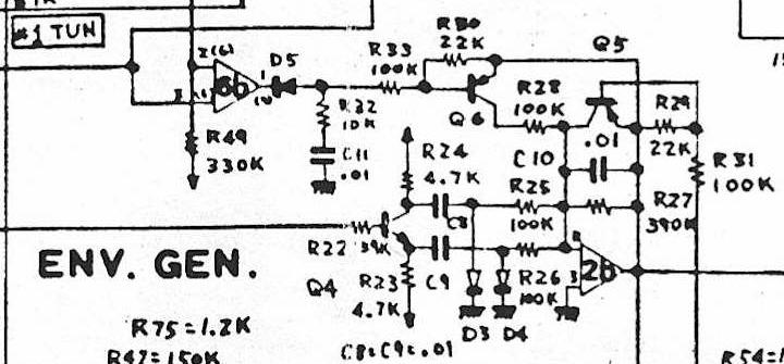
The hexaphonic guitar signals also go into six circuits that output a voltage proportional to the cycle period of the guitar string's oscillation. Each string's circuit is calibrated so that the open string pitch produces a voltage of 10 volts, a note an octave higher produces 5 volts, another octave higher produces 2.5 Volts, etc. This period CV is at "TP-1" in the above schematic.
On a vibrating guitar string, the second harmonic frequently becomes louder than the fundamental during long notes. This often confuses pitch tracking circuits into thinking the player has suddenly played a note an octave higher. The result is an unwanted octave jump in the synthesizer sound. Great pains have been taken in the GR-300's design to prevent this problem:
At the input of the pitch tracking circuit are two analog bandpass filters to suppress the second harmonic (circled in red on the schematic). When notes below the sixth fret are played, the cutoff frequencies of the filters are both near the open string pitch. When notes above the sixth fret are played, the filters move to frequencies higher up the neck.
Another circuit later in the chain detects the sudden changes in period voltage that occur when the second harmonic gets as loud as the fundamental (circled in yellow on the schematic). When it sees these changes, it reduces the output voltage from the envelope follower, which in turn reduces the volume of the synth sound to make the problem less noticeable.
I am working toward a synthesizer consisting of the GR-300 itself plus two additional boxes:
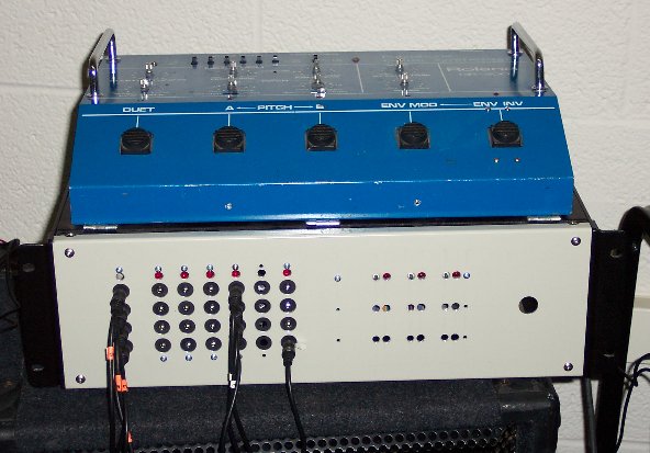
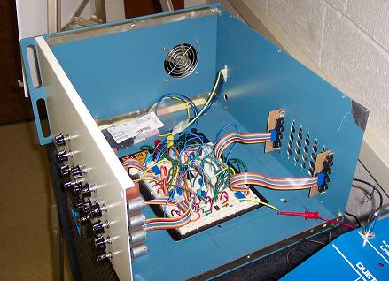
(The Converter Box so far)
The GR-300 sits on top of a rack mount chassis I will call the Converter Box. On the right side of the front panel is a 13-pin DIN jack for connection to the Roland-GK-2-compatible synth pickup on the user's guitar. On the left side of the front panel are 7 columns of 3.5mm jacks. Each column outputs the following control voltages derived from one string of the guitar:
The far left column of jacks is a monophonic output with "loudest-string priority". This means that when the user plays one note, the control signals for that note will come out of these jacks regardless of which string the note is played on. When these signals are used to control an external monophonic analog synthesizer (like my ARP Axxe), the player can play a single-note line across any the strings and the synth will follow it.
The next six columns of jacks are the individual outputs for strings, 1-6.
Three rows of pushbuttons and LEDs on the front panel are used to control various functions inside the Converter Box.
(The Synth Box so far)
A second larger rackmount chassis I will call the Synth Box (which is only partially finished) will contain a polyphonic analog synthesizer minus the oscillators. On the back panel there will be a grid of 3.5mm jacks identical to the one on the front of the Converter Box. Multiple 3.5mm cables will be run between the two boxes. Buttons and pots on the front of the Synth Box are used to control the various synthesizer parameters.
When the boxes are connected, the result will be a fully polyphonic synthesizer with each guitar string driving one voice. Each voice has voice will feature the following:
The pots are all motorized and the circuits are designed so that computer control can be added eventually.
The GR-300 sits atop this box which contains a power supply and two boards I call WWB1 (Wire-Wrap Board #1) and WWB2 ( Wire-Wrap Board #2).
Here is a block diagram of the Converter Box and its connections to the outside world:
                                                            Converter Box
  ┌────────────────────────────────────────────┐     ┌─────────────────────────┐
  │            GR─300               Variable─  │     │                         │
  │   Envelope       Period         Amplitude  │<────┤ GK2─to─GR─300 Interface │<─── Guitar
  │   Followers      Control        Sawtooth   │     │                         │
  │                  Voltages       Waveforms  │     │                         │
  │                                            │     │                         │
  │  1 2 3 4 5 6    1 2 3 4 5 6    1 2 3 4 5 6 │     │                         │
  └──┬─┬─┬─┬─┬─┬────┬─┬─┬─┬─┬─┬────┬─┬─┬─┬─┬─┬─┘     │                         │
     │ │ │ │ │ │    │ │ │ │ │ │    │ │ │ │ │ │       │                         │
     │ │ │ │ │ │    │ │ │ │ │ │    │ │ │ │ │ │       │                         │
┌────│─│─│─│─│─│────│─│─│─│─│─│────│─│─│─│─│─│───────┘                         └─────────────────┐
│    │ │ │ │ │ │    │ │ │ │ │ │    │ │ │ │ │ │                                                   │
│    │ │ │ │ │ │    │ │ │ │ │ │    │ │ │ │ │ │         Button Boards & Flip Flops ───┐           │
│    │ │ │ │ │ │    │ │ │ │ │ │    │ │ │ │ │ │                                       V           │   ┌─────┐
│    │ │ │ │ │ │    │ │ │ │ │ │    │ │ │ │ │ │     Waveform                       Waveform       │   │     │
│    │ │ │ │ │ │    │ │ │ │ │ │    │ │ │ │ │ │     Converters                     Mix/Amp        │   │     │
│    │ │ │ │ │ │    │ │ │ │ │ │    │ │ │ │ │ │      ┌───┐    ┌───┐                 ┌───┐         │   │     │
│    │ │ │ │ │ │    │ │ │ │ │ │    └─│─│─│─│─│─────>│ 1 │───>│ S ├────────────────>│ 1 ├────────────>│     │
│    │ │ │ │ │ │    │ │ │ │ │ │      └─│─│─│─│─────>│ 2 │───>│ e ├────────────────>│ 2 ├────────────>│     │
│    │ │ │ │ │ │    │ │ │ │ │ │        └─│─│─│─────>│ 3 │───>│ l ├─── New ────────>│ 3 ├────────────>│     │
│    │ │ │ │ │ │    │ │ │ │ │ │          └─│─│─────>│ 4 │───>│ e ├─── Waveforms ──>│ 4 ├────────────>│     │
│    │ │ │ │ │ │    │ │ │ │ │ │            └─│─────>│ 5 │───>│ c ├────────────────>│ 5 ├────────────>│     │
│    │ │ │ │ │ │    │ │ │ │ │ │              └─────>│ 6 │───>│ t ├────────────────>│ 6 ├────────────>│     │
│    │ │ │ │ │ │    │ │ │ │ │ │                     └───┘    │   │                 └───┘         │   │     │
│    │ │ │ │ │ │    │ │ │ │ │ │                              │   ├─── Wave of Loudest String ───────>│     │
│    │ │ │ │ │ │    │ │ │ │ │ │                              ├───┤                               │   │     │
│    o─│─│─│─│─│────│─│─│─│─│─│─────────────────────────────>│ S ├──────────────────────────────────>│     │
│    │ o─│─│─│─│────│─│─│─│─│─│─────────────────────────────>│ e ├──────────────────────────────────>│     │
│    │ │ o─│─│─│────│─│─│─│─│─│─────────────────────────────>│ l ├─── Envelope ─────────────────────>│  3  │
│    │ │ │ o─│─│────│─│─│─│─│─│─────────────────────────────>│ e ├─── Follower ─────────────────────>│  .  │
│    │ │ │ │ o─│────│─│─│─│─│─│─────────────────────────────>│ c ├─── Signals ──────────────────────>│  5  │
│    │ │ │ │ │ o────│─│─│─│─│─│─────────────────────────────>│ t ├──────────────────────────────────>│     │
│    │ │ │ │ │ │    │ │ │ │ │ │                              │   │                               │   │  m  │
│    │ │ │ │ │ │    │ │ │ │ │ │                              │   ├─┬─ EF of Loudest String ─────────>│  m  │
│    │ │ │ │ │ │    │ │ │ │ │ │                              └───┘ │                             │   │     │
│    │ │ │ │ │ │    │ │ │ │ │ │   6 Basic EF/Gate              ^   │  ┌─────────────────────┐    │   │     │
│    │ │ │ │ │ │    │ │ │ │ │ │   Converters                   │   └─>│Improved EF/Gate Conv├───────>│     │
│    │ │ │ │ │ │    │ │ │ │ │ │     ┌───┐                      │      └─────────────────────┘    │   │  J  │
│    o─│─│─│─│─│────│─│─│─│─│─│────>│ 1 ├───────────────────────────────────────────────────────────>│  a  │
│    │ o─│─│─│─│────│─│─│─│─│─│────>│ 2 ├───────────────────────────────────────────────────────────>│  c  │
│    │ │ o─│─│─│────│─│─│─│─│─│────>│ 3 ├──────────────────────────── Gate ─────────────────────────>│  k  │
│    │ │ │ o─│─│────│─│─│─│─│─│────>│ 4 ├──────────────────────────── Signals ──────────────────────>│  s  │
│    │ │ │ │ o─│────│─│─│─│─│─│────>│ 5 ├───────────────────────────────────────────────────────────>│     │
│    │ │ │ │ │ o────│─│─│─│─│─│────>│ 6 ├───────────────────────────────────────────────────────────>│     │
│    │ │ │ │ │ │    │ │ │ │ │ │     └───┘                      │                                 │   │     │
│    │ │ │ │ │ │    │ │ │ │ │ │                                │                                 │   │     │
│    │ │ │ │ │ │    │ │ │ │ │ │     6 Log                    ┌─┴─┐                               │   │     │
│    │ │ │ │ │ │    │ │ │ │ │ │   Converters                 │   │                               │   │     │
│    │ │ │ │ │ │    │ │ │ │ │ │     ┌───┐                    │ S │                               │   │     │
│    │ │ │ │ │ │    └─│─│─│─│─│────>│ 1 ├───────────────────>│ e ├─── 1 Volt ───────────────────────>│     │
│    │ │ │ │ │ │      └─│─│─│─│────>│ 2 ├───────────────────>│ l ├─── Per ──────────────────────────>│     │
│    │ │ │ │ │ │        └─│─│─│────>│ 3 ├───────────────────>│ e ├─── Octave ───────────────────────>│     │
│    │ │ │ │ │ │          └─│─│────>│ 4 ├───────────────────>│ c ├─── Control ──────────────────────>│     │
│    │ │ │ │ │ │            └─│────>│ 5 ├───────────────────>│ t ├─── Voltages ─────────────────────>│     │
│    │ │ │ │ │ │              └────>│ 6 ├───────────────────>│   ├──────────────────────────────────>│     │
│    │ │ │ │ │ │                    └───┘                    │   │                               │   │     │
│    V V V V V V                                             │   ├─── CV of Loudest String ─────────>│     │
│   ┌───────────┐                                            └───┘                               │   │     │
│   │  Loudest  │                                              ^                                 │   └─────┘
│   │  String   │                                              │                                 │
│   │  Detector ├──────────────────────────────────────────────┘                                 │
│   └───────────┘                                                                                │
│                                                                                                │
└────────────────────────────────────────────────────────────────────────────────────────────────┘
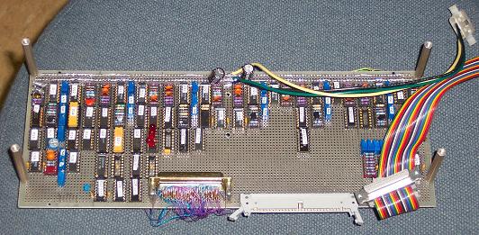
WWB1 (Wire-Wrap Board #1)
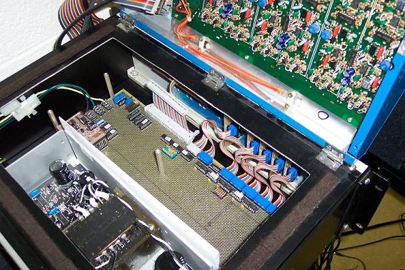
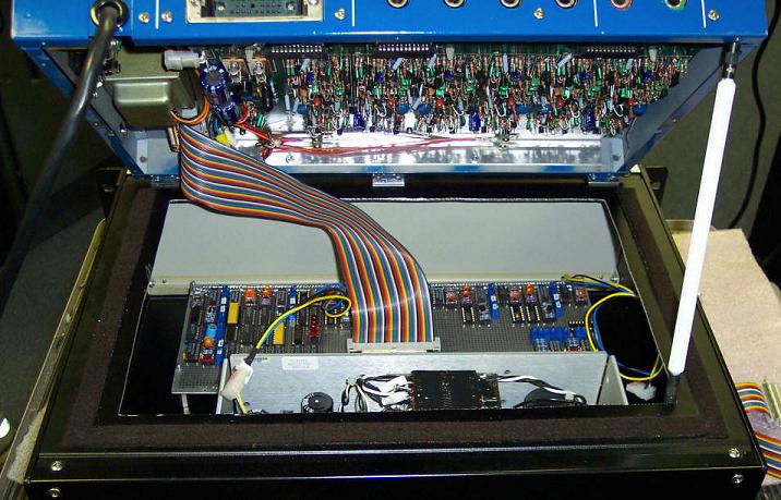
WWB2 (Wire-Wrap Board #2) inside the Converter Box with WWB1 removed
The bottom board of the GR-300, which contains the pitch tracker and envelope follower circuits, has been modified with extra connections running to a DB-50 connector inside the blue box. A ribbon cable runs to another DB-50 connector on WWB1.
WWB1 is mounted directly atop WWB2 and is connected to it via a 60-pin ribbon cable.
WWB1 contains the following circuits:
WWB2 has space for 12 waveform converter boards and associated waveform-mixer and dynamics circuitry. It also contains 14-pin DIP sockets that lead through DIP connectors and ribbon cables to the following small circuit boards mounted on the front panel of the Converter Box:
For maximum timbral flexibility, it is desirable to have a separate filter on each string that tracks the string's pitch. The GR-300 lacks these. It is also desirable to be able to control external analog synth hardware with the GR-300's pitch tracker. These things are both made difficult by the fact that the pitch control voltage scheme used inside the GR-300 is non-standard. The pitch-associated control voltages present are proportional to the PERIOD (cycle time) of the guitar string. Most analog synth circuitry uses a logarithmic 1-volt-per-octave control voltage scheme instead. So in order to interface the two, a log converter circuit is necessary. Six copies of the circuit are wired on WWB1.
For details about this circuit, go to this URL:
http://www.marksmart.net/gearhack/gr300/analogmods/logconverter/logconverter.html
One problem with the old Roland guitar synths is that you have to use a specially made Roland synth guitar to play them. I designed a circuit which will allow you to play an old Roland guitar synth from a guitar with a newer GK-2(a)-style pickup. One copy of this circuit is built on WWB1.
For details about this circuit, go to this URL:
http://www.marksmart.net/gearhack/gr300/analogmods/gk2gr300interface/Gk2Gr300Interface.html
Most synthesizers use "gate" signals, high-or-low signals indicating that a note is currently sounding. These are used to trigger envelope generators which can modulate various synth parameters over the chouse of a note.
There are no gate signals present inside the GR-300, so external circuitry must be used to derive these from the envelope follower outputs.
The simplest way to generate gates would be to use a comparator whose output goes high when the envelope follower voltage is above some set value. But this will not work well here. The ripple on the envelope follower voltage will cause the gate signal to bounce up and down several times as the note is dying out, triggering unwanted extra notes from the synthesizer. So the first version of an envelope-to-gate converter circuit I designed was a hysteresis comparator: a comparator whose threshold level changes to a different value as soon as its output changes state.
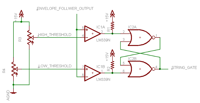
Before the note begins, the comparator's threshold voltage is at a higher level (adjustable with a trimpot) slightly below the volume of the guitar string right after the attack of a soft note. After the attack, the threshold jumps to a lower level slightly above zero (also adjustable). When the note dies out and the input voltage crosses below this low threshold for the first time, the threshold jumps back to the high level, preventing the output from bouncing as the input oscillates around the lower threshold several times.
There are now six copies of this circuit on WWB1, one per string, and their outputs go to the Gate jacks for the individual string outputs on the Converter Box's front panel.
The basic converter works fairly well, but it suffers from a few problems. If a series of notes are picked rapidly on the same string, the envelope follower output does not always die down below the lower threshold, so the synthesizer will not re-attack the notes as desired. If the low threshold is raised, then the gate signal will go low while the guitar string is still vibrating fairy loudly, cutting off the synth sound too soon.
To solve these problems I designed an improved envelope-to-gate converter containing an attack-decay envelope generator whose output follows closely underneath the envelope of the guitar string as the note decays.
For details about this circuit, go to this URL:
http://www.marksmart.net/gearhack/gr300/analogmods/envgateconverter/envgateconverter.html
One copy of this circuit is currently wired on WWB1. Its input is the envelope follower of whichever string is currently ringing the loudest as determined by the Loudest String Detector (see below). Its output goes to the Gate jack of the monophonic output on the Converter Box's front panel.
Since many analog synthesizers are monophonic, it is desirable to derive monophonic control voltage, gate, and envelope follower signals from the GR-300 to control them. I designed a circuit which determines which string is playing the loudest note at that moment and outputs a binary value between 0 and 5 indicating the loud string. This value can be used to control which string's signals get sent to the monophonic output. In this way, a single-note solo played across multiple guitar strings can be used to control an external analog synthesizer.
For more information about this circuit:
http://www.marksmart.net/gearhack/gr300/analogmods/loudeststring/loudeststring.html
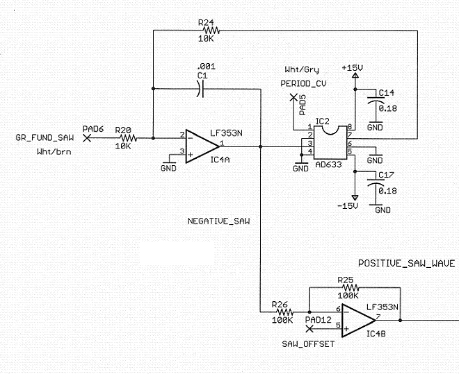
Inside the GR-300, the only audio waveforms available come from the integrators used to measure the period of the guitar string. These are ascending sawtooth waves that start at 0V and ramp up to a voltage between 2.5V and 10V depending on the cycle period of the guitar note (circled in green in the GR-300 pitch tracker schematic at the beginning of this document). These are not useful for a standard analog synth setup (with a voltage-controlled amplifier at the end) because low notes are much louder than high ones. To generate the audio waveforms usually available in analog synthesizers (constant-amplitude sawtooth, pulse, and triangle) some converter circuits are needed. I designed a circuit that does all three conversions, then designed a small PC board containing it. To date I have built and tested two of the boards. The intention is to eventually have 12 of these boards, 2 per string.
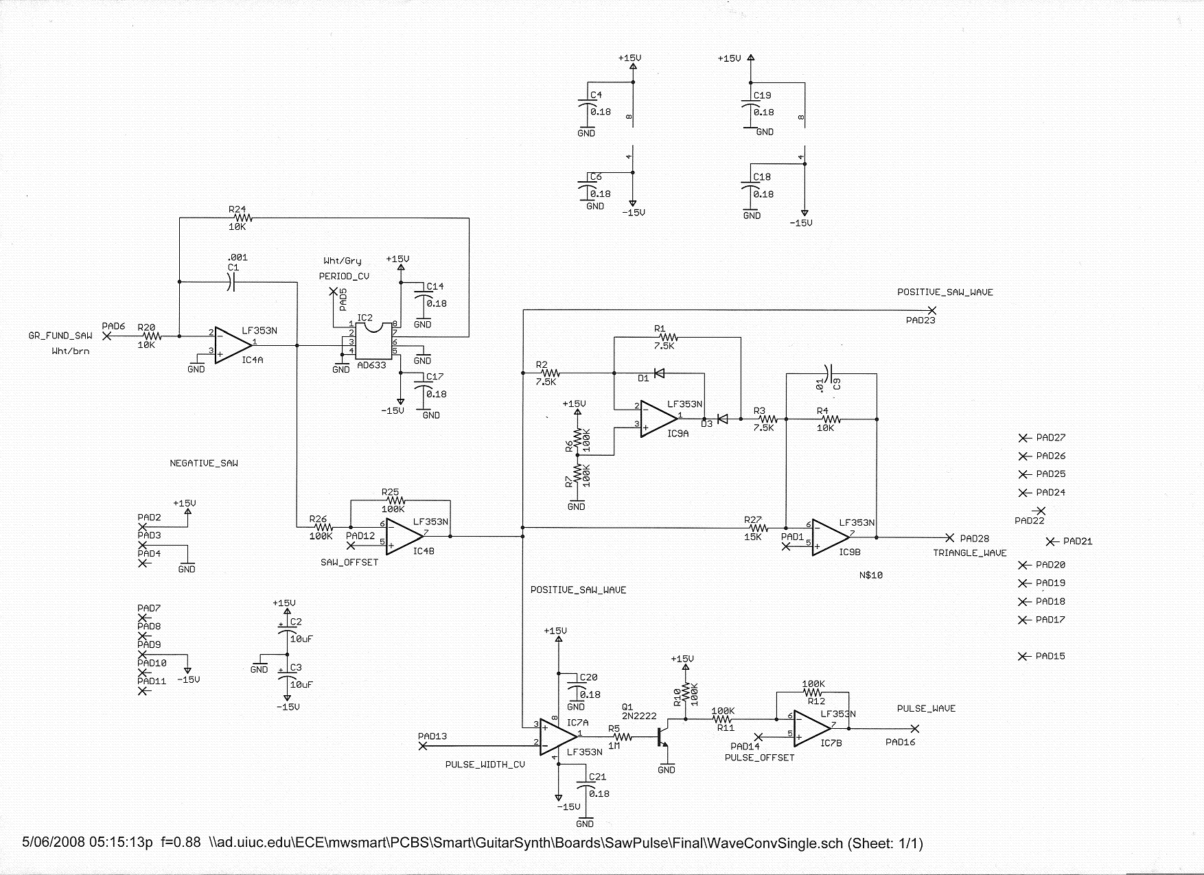
The circuit has three parts. Each part has an offset adjustment so the waveform can be set to oscillate around +7.5 volts, facilitating later waveform selection using a CD4016 analog switch IC that can only handle positive voltages. Special thanks to Skot Wiedmann, analog designer extraordinaire, for help on these circuits.
This circuit uses the variable-amplitude sawtooth and period CV signals from the GR-300 to generate a sawtooth wave of constant amplitude. It is an analog divider formed by putting an AD633 analog multiplier chip in the feedback loop of an LF353 op-amp. The period CV from the GR-300 is the peak value attained by the integrator in the previous cycle. During sustained tones the peaks of consecutive cycles of the integrator are the same. Therefore, dividing the current integrator output by the period CV will give a sawtooth of the same height during tones longer than a few milliseconds.
This is merely a comparator that compares the ascending sawtooth from the sawtooth converter with an incoming CV that indicates the desired pulse width of the output waveform. The pulse width CV comes from a knob on the Synth Box and is sent to all the waveform converter boards.
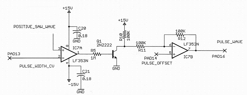
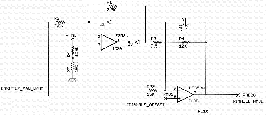
This is a full-wave rectifier that rectifies the ascending sawtooth around 7.5V, then lowpass filters it a bit to get rid of discontinuities at the transition point.
Control logic allows the user to select any or all of the triangle, sawtooth, or pulse waveforms to go to the waveform output.
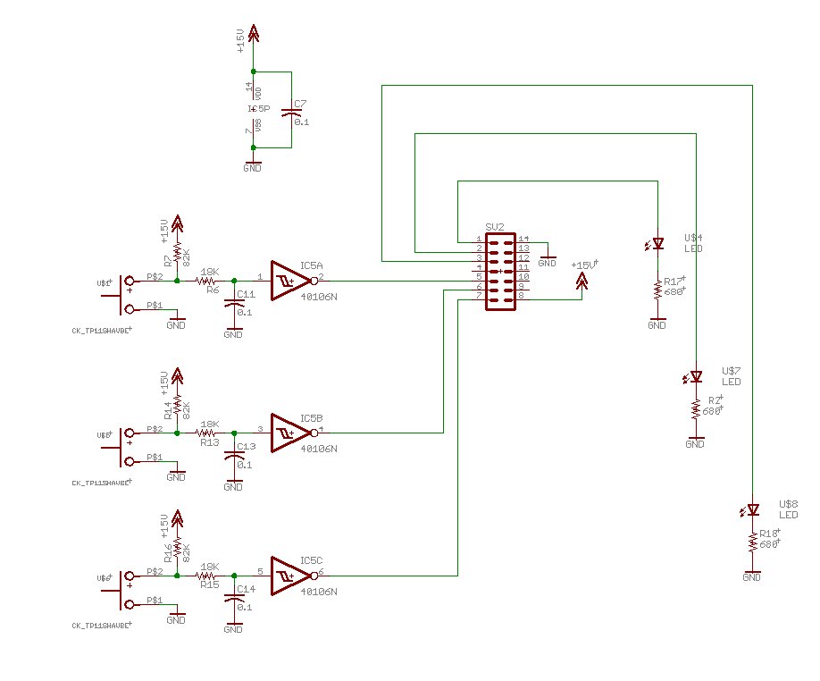
The front panel of the Converter Box has three Button Boards, small boards that each contain three buttons, 3 LEDs and three pushbutton debouncer circuits. These are each connected through a ribbon cable and 14-pin DIP connectors to WWB2.
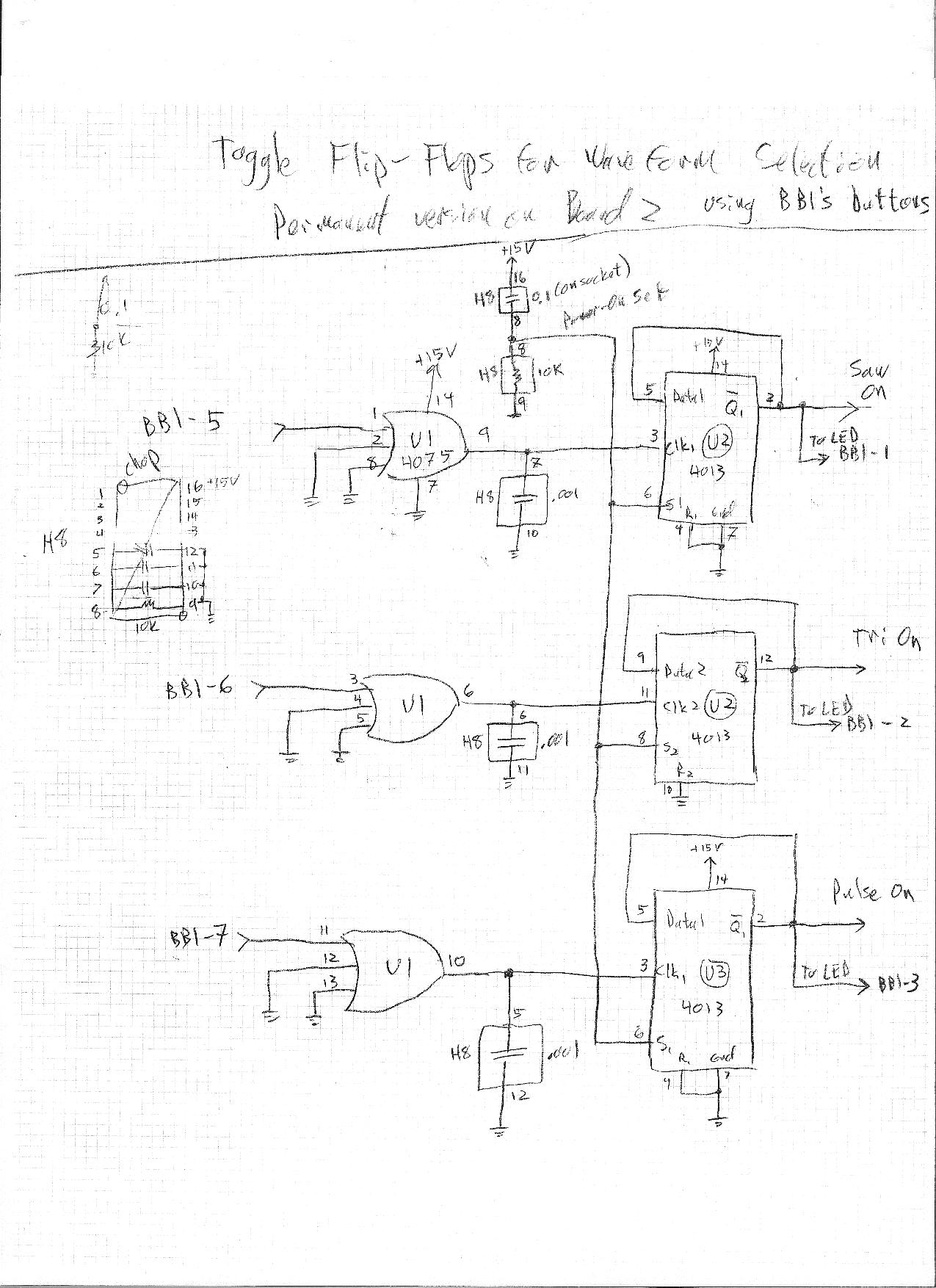
The debounced button signals from the button boards drive three toggle flip-flop circuits on WWB2. The flip-flops are used to control the waveform mixer and light up the LEDs on the button boards when high.
At present only one of the button boards has flip-flops. They are controlling the sawtooth, triangle, and pulse wave outputs on the Waveform Mixer.
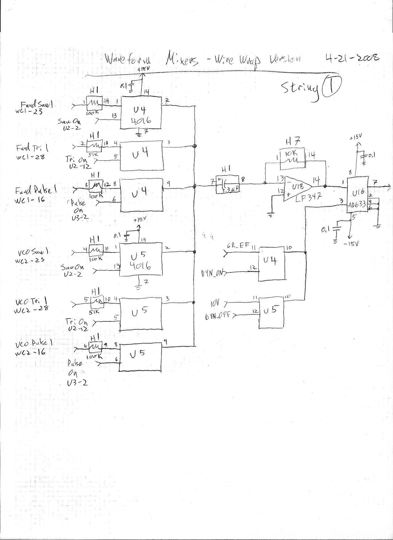
The control signals from the flip-flops activate 4016 analog switch chips that determine whether each of the waveforms gets to the output. The waveforms all have a +7.5 VDC offset so they will not be sending negative voltages through these chips. After the analog switches is a blocking capacitor to remove the DC offset.
Finally there is an AD633 multiplier controlling the amplitude of the output. This can either pass the waveform signal unchanged ("dynamics off" mode) or multiply it by the envelope follower voltage ("dynamics on" mode"). Currently this is hard wired in "dynamics off" mode, but the intention is to use another button from the front panel to allow the used to turn dynamics on or off. In cases where the amplitude of the waveform is being modulated further downstream in the audio path, it may be more useful for this part to be outputting at full volume all the time.
The Synth Box currently contains a breadboard version of the circuits for one voice, based around the CEM3391 analog synthesizer voice chip made by Curtis in the 1980s. The intention is to eventually build six complete copies of the circuit in this box.
Here is a block diagram of the circuits for one voice in the Synth Box
         ┌──────────────────────────────────────────────────────────────────────────────────────┐
         │                                                                                      │
┌─────┐  │                                                        ┌──────────────────┐          │
│     │  │                                                        │   CEM 3391       │          │
│     │  │ 1 V/O CV        ┌─────────┐   ─0.5 V/O CV     ┌───┐    │                  │          │
│     │───────────────────>│ Convert │──────────────────>│   │    │                  │          │
│     │  │                 └─────────┘                   │   │    │                  │          │
│     │  │                                               │   │    │                  │          │
│     │  │                                               │   │    │                  │          │
│     │  │          Filter Cutoff Knob ─────────────────>│ + │───>│ Cutoff           │          │
│     │  │                                               │   │    │                  │          │
│     │  │                                               │   │    │                  │          │
│     │  │ Envelope Follower          ┌───┐              │   │    │                  │          │
│     │─────────o────────────────────>│   │─────────────>│   │    │                  │          │
│  3  │  │      │   EF Depth Knob ───>│ X │              └───┘    │                  │    ┌───┐ │
│  .  │  │      │                     │   │                       │           Audio  │───>│   │──────> Audio
│  5  │  │      │                     └───┘                       │           Out    │    │ X │ │   Out
│     │  │      │                                                 │                  │    │   │ │
│  m  │  │      └──────────────────────────────────────────────── │ ─  ─  ─  ─  ─  ─ │ ──>│   │ │
│  m  │  │                                                        │                  │    └───┘ │
│     │  │                                                        │                  │          │
│  J  │  │ 15V Gate          ┌─────────┐     5V Gate              │                  │          │
│  a  │─────────────────────>│ Convert │─────────────────────────>│ Gate             │          │
│  c  │  │                   └─────────┘                          │                  │          │
│  k  │  │                                                        │                  │          │
│  s  │  │ Waveforms                                              │                  │          │
│     │──────────────────────────────────────────────────────────>│ Audio In         │          │
│     │  │                                                        │                  │          │
│     │  │                        Attack Knob ───────────────────>│ Attack           │          │
│     │  │                        Decay Knob ────────────────────>│ Decay            │          │
│     │  │                        Sustain Knob ──────────────────>│ Sustain          │          │
│     │  │                        Release Knob ──────────────────>│ Release          │          │
│     │  │                                                        │                  │          │
│     │  │                        ADSR Filter Depth Knob ────────>│ ADSR Depth       │          │
│     │  │                        Resonance Knob ────────────────>│ Resonance        │          │
│     │  │                                                        │                  │          │
│     │  │                        Volume Knob ───────────────────>│                  │          │
│     │  │                                                        │                  │          │
│     │  │                                                        └──────────────────┘          │
└─────┘  └──────────────────────────────────────────────────────────────────────────────────────┘
The front panel of the Synth Box currently has potentiometers to control the following parameters:
Here is a schematic of the CEM3391 and its associated interface circuits:
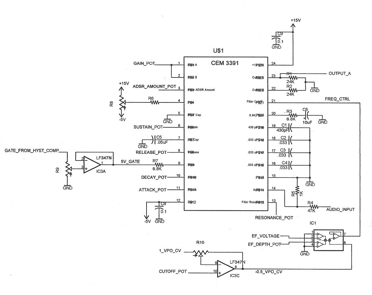
The cutoff frequency of the CEM3391's lowpass filter always tracks the pitch of the guitar string. It can also be modulated from three other sources:
One of the CV inputs of the CEM3391 controls the depth of modulation of the cutoff frequency by the internal ADSR, so no external circuitry is needed except a depth knob on the front panel.
Inconveniently, like the GR-300, the CEM3391 has an unusual pitch control voltage scheme, except this one is logarithmic and is -0.5V/octave. Therefore, the 1V/octave CVs from the Converter Box must be multiplied by -0.5 for proper filter tracking. An op-amp buffer stage with tunable gain takes care of this.
On acoustic instruments, loud notes have a brighter timbre than soft notes, adding considerably to the expressiveness of the instrument. On a synthesizer it is desirable to be able to modulate the filter cutoff with the envelope follower voltage (loudness) to imitate this effect. I used another AD633 to multiply the incoming envelope follower voltage by a depth CV coming from a knob on the Synth Box's front panel.
The two above signals plus a CV from the Filter Cutoff knob on the front of the Synth Box get added together in the AD633 chip and sent into the Filter Cutoff CV input of the CEM3391.
The CEM3391 expects a 5 volt gate signal rather than the 15V signal being output by the Converter Box. Also, the CEM3391 responds intermittently to the gate signal unless it is buffered first. So this circuit reduces the gate voltage and buffers it before sending it into the CEM3391's gate input.
I had intended to use the final VCA of the CEM3391 to control the synth's volume level with the envelope follower voltage from the Converter Box. There was, however, a problem. When the user is not playing a note, the Period CVs from the GR-300 oscillate erratically, not able to center on a pitch. This oscillation percolates through the system and shows up on the filter cutoff input of the CEM3391. Unfortunately, this produces audible noise at the output of the CEM3391 even when its final VCA is completely shut off. So I added another AD633 after the CEM3391 that takes care of the dynamics of the synth signal and shuts off the noise when no notes are played.
My use of these CEM3391 chips in this project ended up being a mistake. I had never tested them and assumed they would just work because even though they are 20 years old, they had never been used or even removed from the packing tube. I had a tube of twelve of these, and only 2 of them ended up being fully functional. Two more only partly work and the rest output no sound whatsoever. Apparently these were made using a new process in the 1980s which had not been perfected yet.
As a result, I am not able to complete all six voices of the polyphonic synthesizer at this time. I do have one voice circuit working on a breadboard inside the Synth Box and have been driving it from the Converter Box's monophonic output. It sounds great, I wish I could make 6 of them!
I will have to use some other means to make a fully polyphonic synth, possibly designing small circuit boards that contain circuits equivalent to the components of the CEM3391.
Much of this work was done on my own before taking this class. The parts that were done in the class during this semester were as follows:
That's the extent of the project so far. Have a nice day!