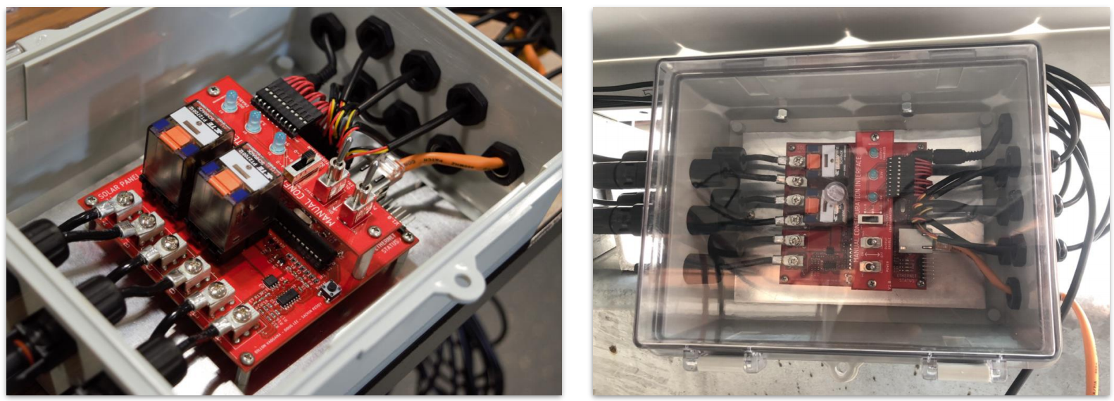
Solar Panel Relay - Original Boards
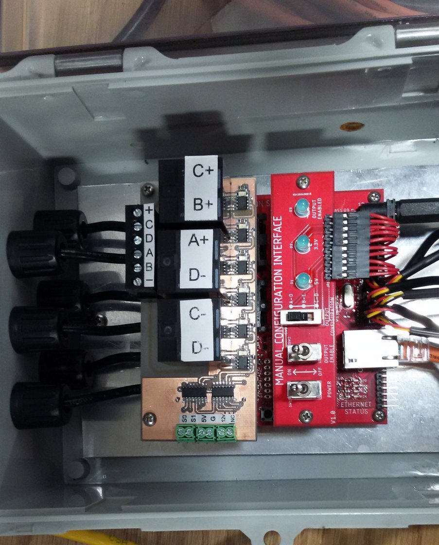
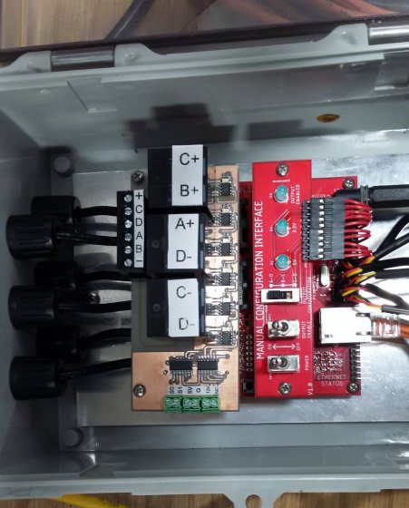
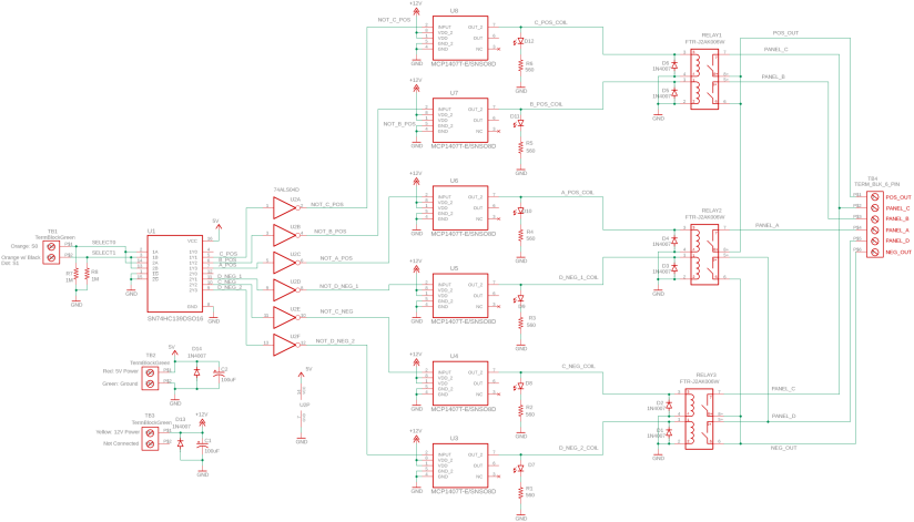
Solar Panel Relay - Mezzanine Board
|
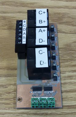
In the summer of 2021, I was asked to design a board to sit on top of
their board (a "mezzanine board") that would allow better relays to be controlled by the red board. In the image, my
milled prototype is sitting on top of the student board (not yet connected).
|
|
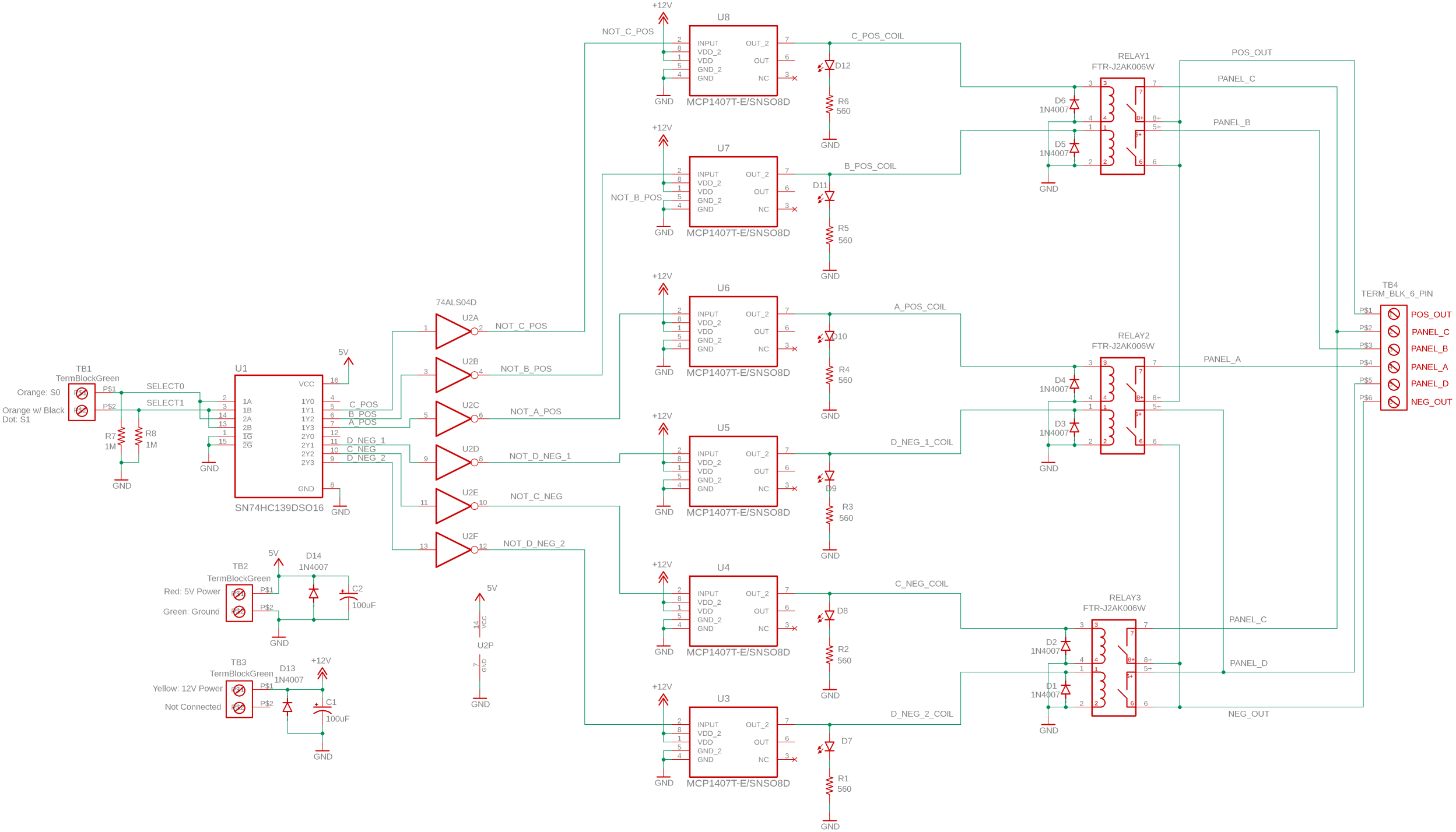
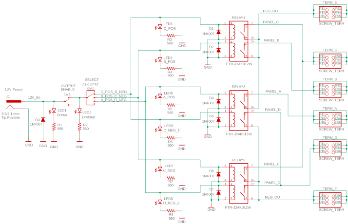
Mezzanine Board Schematic
|
|
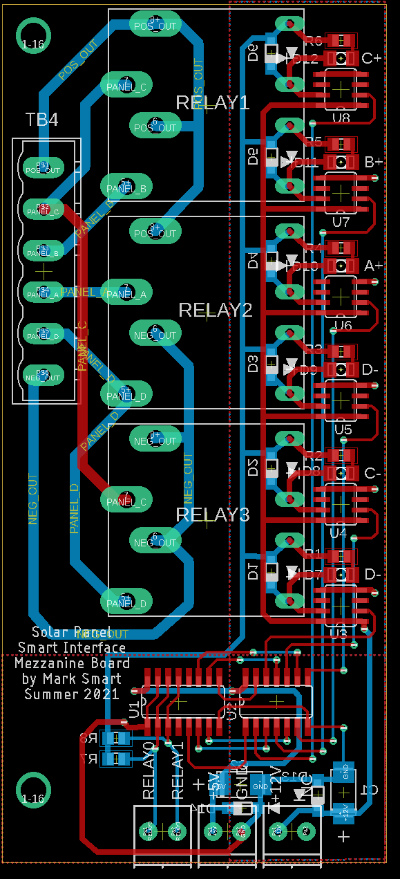
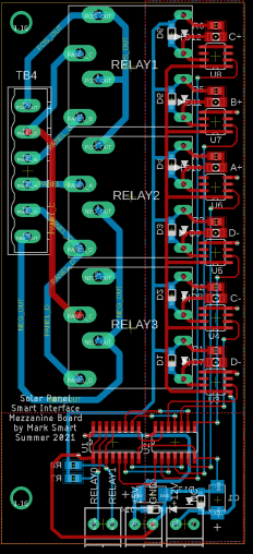
Mezzanine Board Layout
|
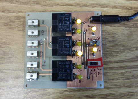
Mezzanine Board Milled Prototype
|
The solar cells on one panel are arranged like this, with the connection points named A, B, C, and D
      ┌──────────┐     ┌──────────┐     ┌──────────┐
   o──┤ 32 Cells ├──o──┤ 64 Cells ├──o──┤ 32 Cells ├──o
   A  └──────────┘  B  └──────────┘  C  └──────────┘  D
It's useful to be able to send different nodes to the + and - terminals going into the power lab from each panel
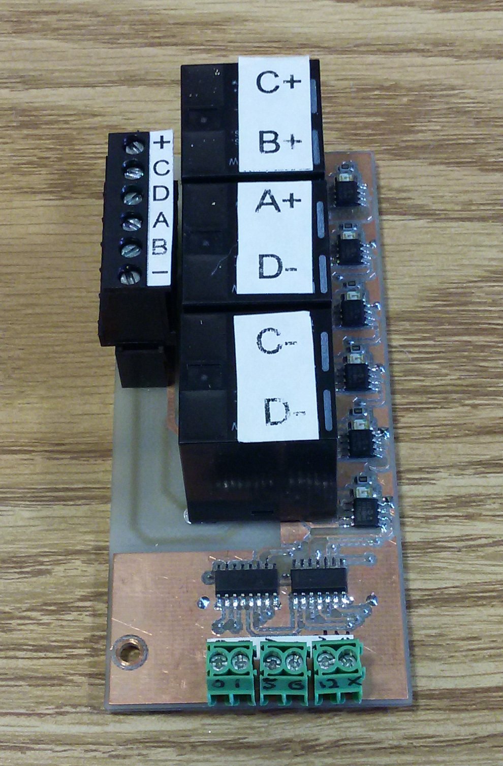
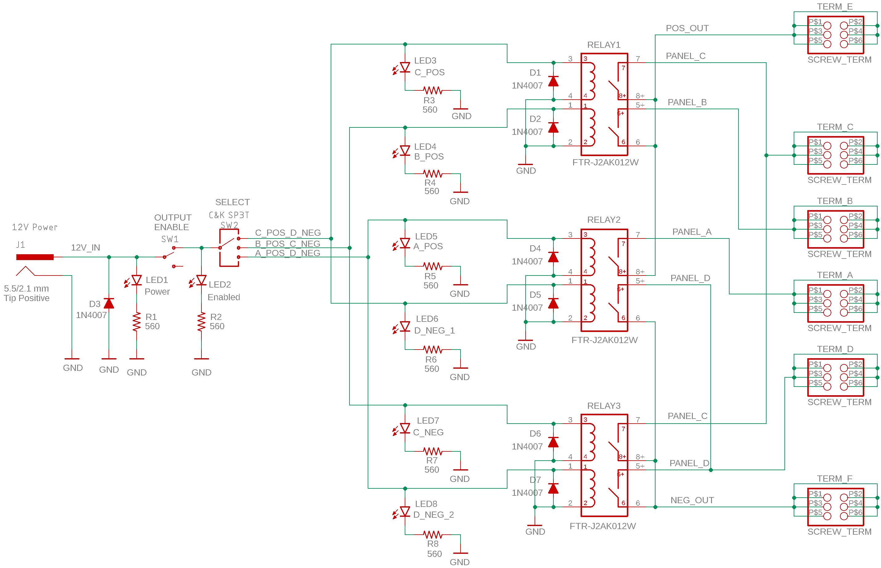
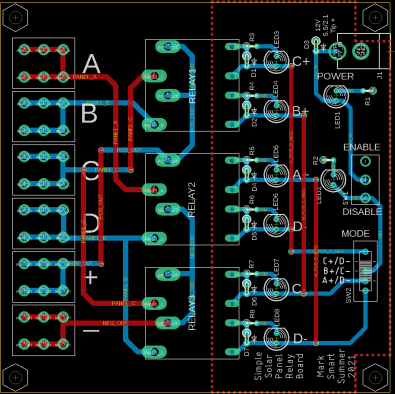
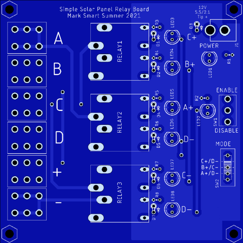
Solar Panel Relay - Simple Board
There were problems getting the red board to work, however, and it was decided to first make a much simpler board with no brain
to perform the safety disconnection and routing functions (controlling which nodes between solar panels are connected to patch panels inside the power lab) alone.
I designed this board and milled a working prototype. Commercial versions are
being manufactured by PCBWay. When they arrive, they will be assembled by students and installed on all 60 experimental solar panels.
|
Schematic
|
|
Prototype Made on Milling Machine
|
Layout of Final Version
|
|
Commercial PCB Image from PCBWay
|