Solder Protoboard
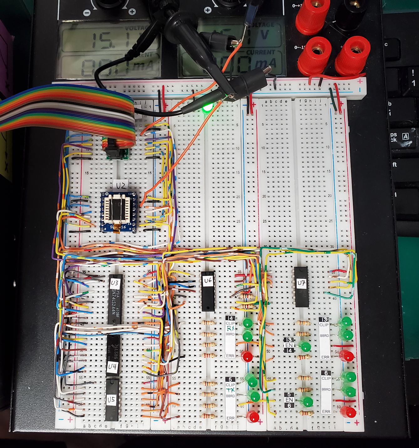
Here is the Logic Comparator built on a powered breadboard. For builds like this I like to use 24-gauge 50-conductor telephone wire and lay the wires down neatly.
Connected to Duplex Test Box
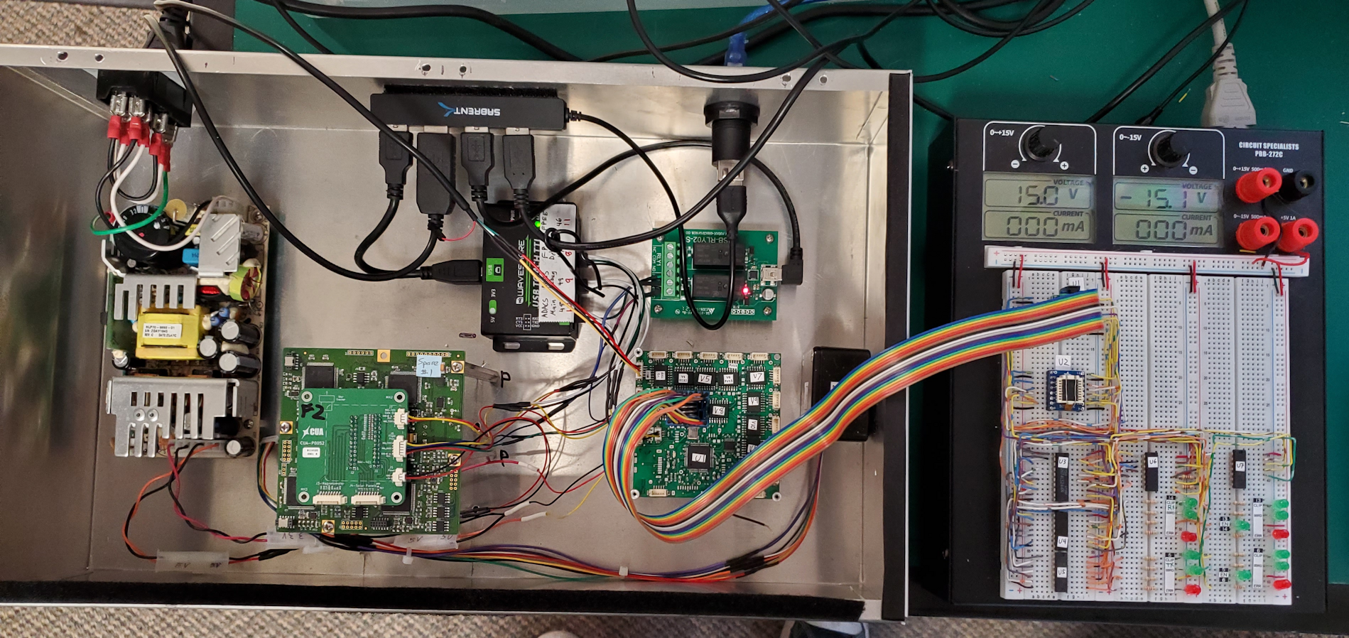
Here the logic comparator is attached to the Duplex test box. The test clip is attached to the 1402 driver chip we are currently testing.
Schematics
|
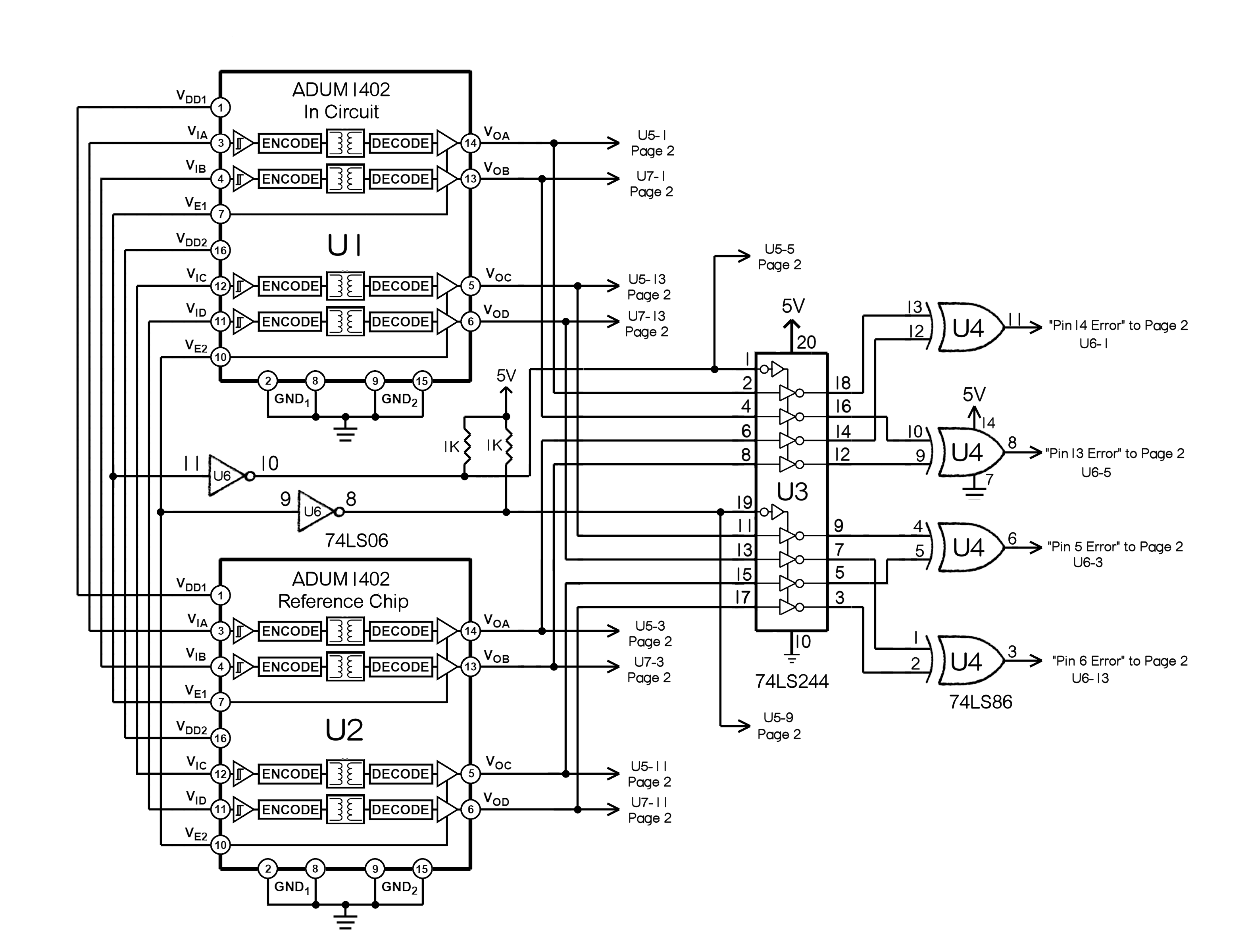
Schematic Page 1 - Comparator Logic. The chip on the upper left is the chip on the PCB in the Duplex Test Box. The one on the lower left is the reference chip U2 on the logic comparator protoboard. The tri-state buffer U3 makes sure that the comparator is only connected to the chips' outputs when their enable lines are high. The XOR gates compare the outputs of the in-circuit and reference chips and light up a red LED if they are different on that output pin. |
|
|
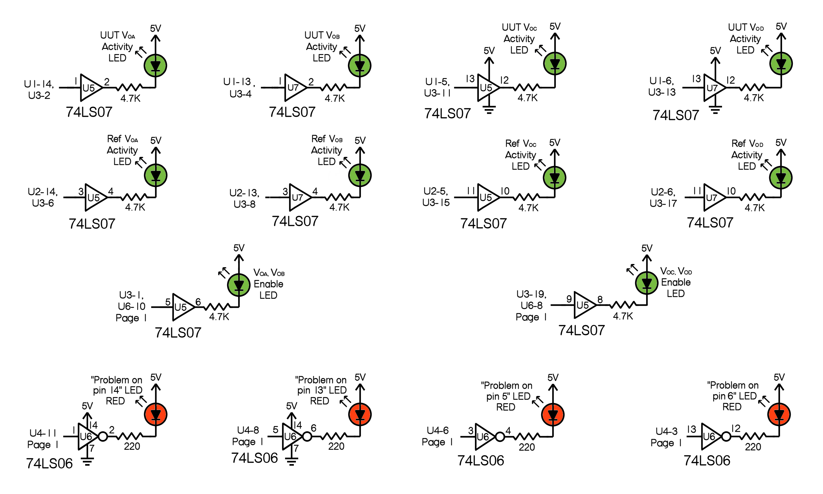
Schematic Page 2 - Indicator LEDs. the green LEDs show activity on the signals being tested. The red LEDs indicate a problem, i.e. the the outputs of the in-circuit and reference chips are different. |
|