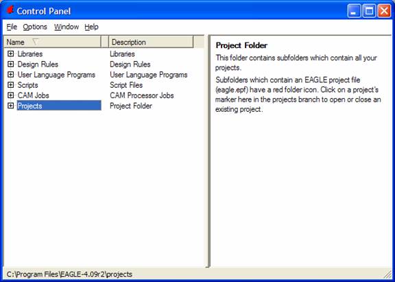
Open the program
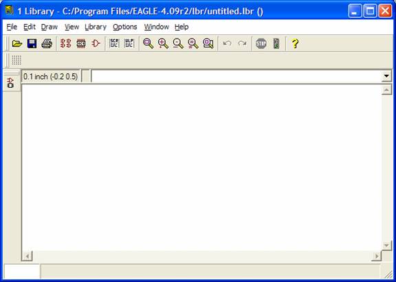
file-> new -> library
OK. now click on the ![]() icon in order to create a Symbol for the part
we are making.
icon in order to create a Symbol for the part
we are making.
Now for an example let’s make a part for the 18f252 SOIC. It looks like this from the data sheet
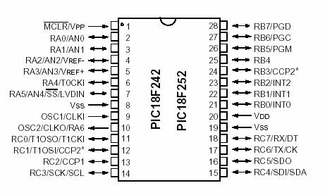
And lets also take a look at the package information as well
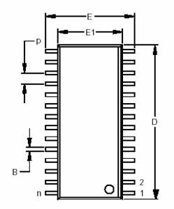
This should be all the information that we need to make the part in eagle.
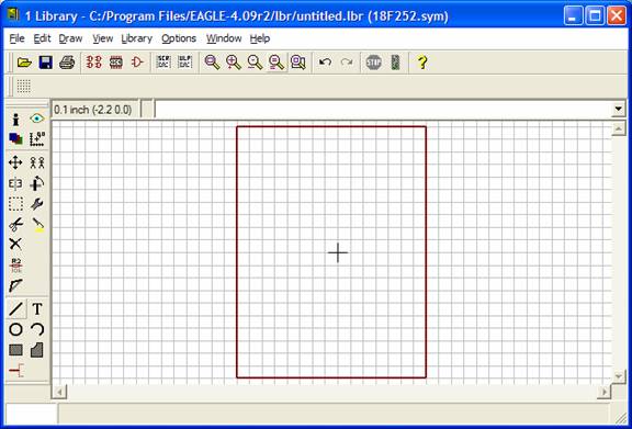
Start first by using the line tool to draw a square
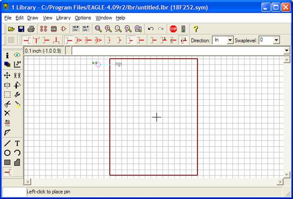
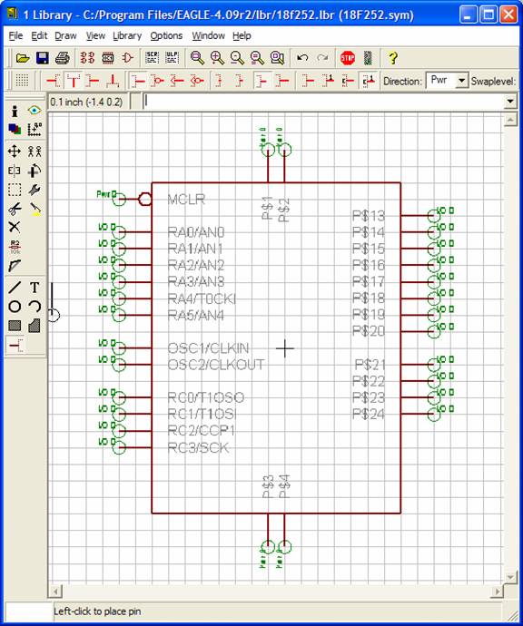
Now let’s add all the pins. We can figure out what we need by looking at the pin list from the data sheet. The first pin lets add the reset pin. Note that it will only be an input therefore set the direction to In first before placing the part. See all the different options we can use for the pin, such as clk and inverted inputs, the direction and even the pin length.
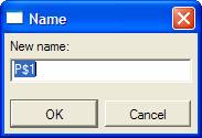
Now using the Name tool lets click on the pin we just added and name the pin. Type MCLR. Note that MCLR in an inverted signal you can use the pin dot in order to represent this.
Now go ahead and add all the pins
>
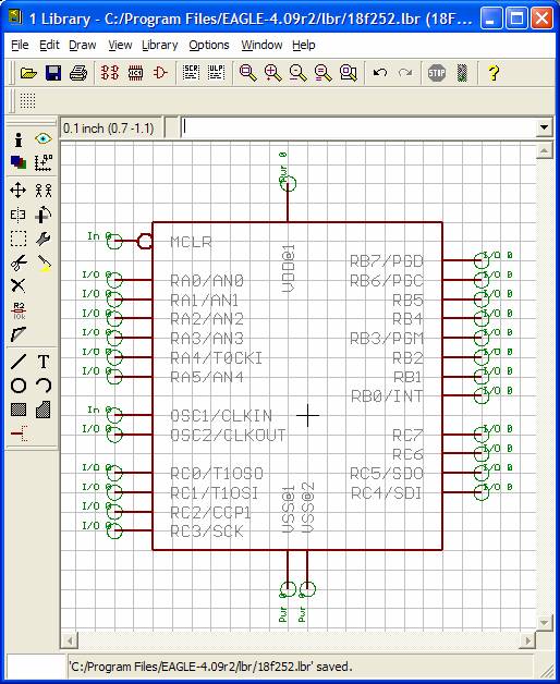
To name VDD and VSS use the naming convention VSS@1 for the first pin and VSS@2 for the second, etc.
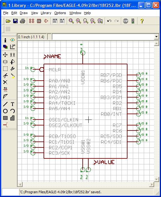
This is how it should look after doing all the pins.
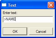
Using the test tool, now let’s add some eagle stuff. When laying down the part it’s nice to include the name and value of a part. Using the > tag allows certain parameters to be placed with the part.
This concludes the symbol generation portion now it should look something like this