First open a new Schematic.

Next add a new part using the ![]() icon
on the toolbar.
icon
on the toolbar.

Go ahead and use the search field to find the Ground symbol. Double click on the GND under supply1 to select that part.
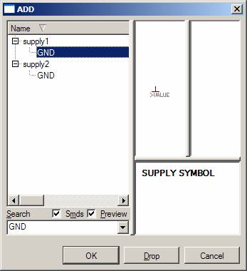
Left-click and place the part somewhere.

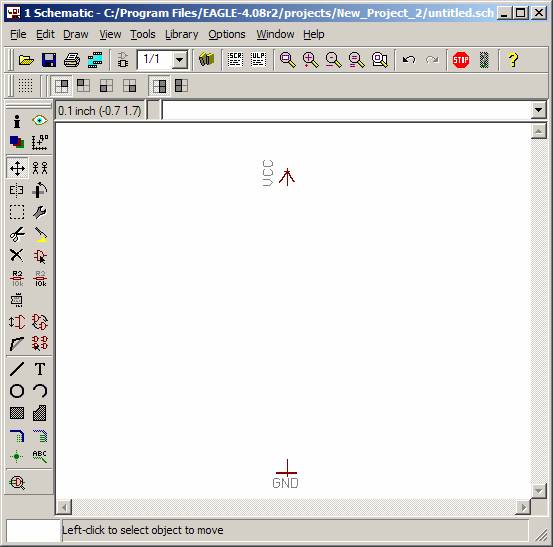
Do the same with Vcc and choose the one
under supply1. You can use the zoom toolbar to navigate around the circuit. ![]() Click
on the left one to auto center the schematic.
Click
on the left one to auto center the schematic.
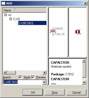
Next add a capacitor. Let’s select a 1uF surface mount capacitor. The normal package for this value is the 1812, pick this one.
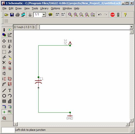
After placing the capacitor lets start connecting the components together. We use the NET tool to connect the GND to the capacitor. Left click to start the wire and double click to end the wire.

After connecting the wires we need to place junctions at where the wire connects to the part. Don’t forget these; they are important to make the connections.
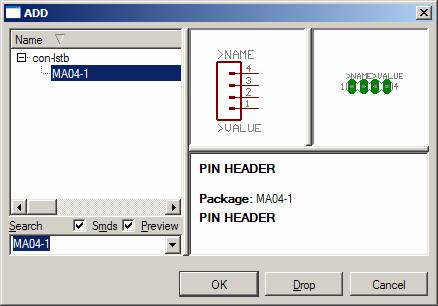
Next add a header. The part name is MA04-1
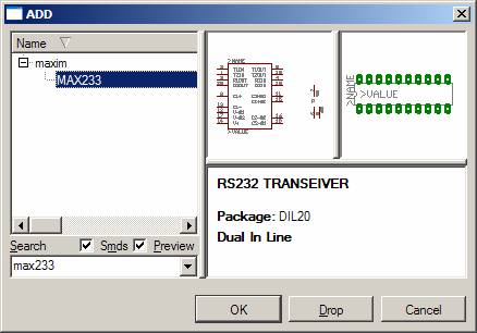
And a MAX233 serial line converter
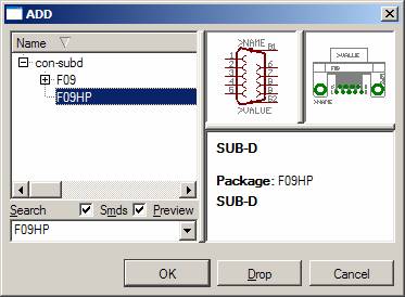
And add the Serial connector. Part is listed as F09HP
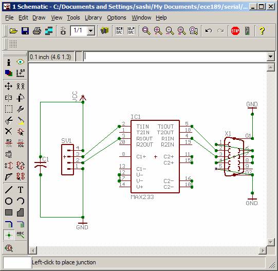
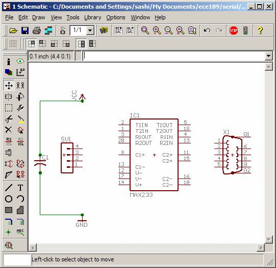
Your schematic should now look something like this
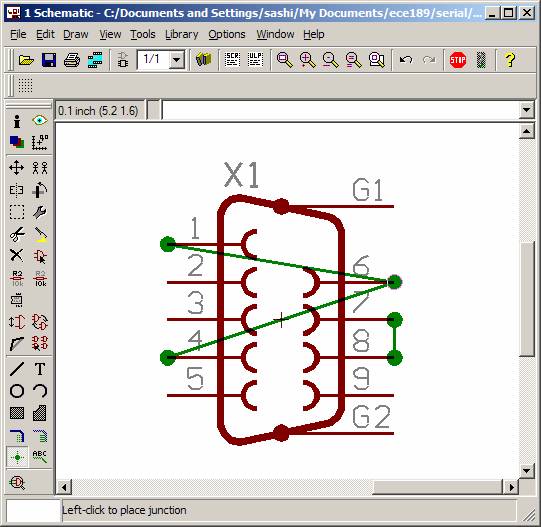
To make the serial port connection to most devices we need to loop-back a couple of signals. Make these connections. 1, 4, 6 shorted together. And 7 and 8 shorted together.
Notice that you can change the way lines are drawn by using the right mouse button. Also don’t forget the Junctions.
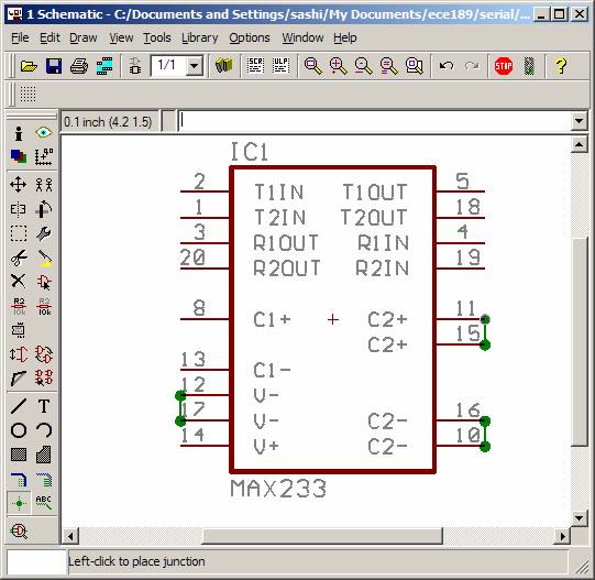
Next we need to configure the MAX233 chip to run the way we want. Short together the C2+ then the C2- and the V-. Leave the rest un-connected. Read the datasheet on the part for more information if you are interested.
Now let’s wire up the header so our chip can get power. Remember in the first step selecting the GND and VCC parts. This allows us to connect power to any chips that need power. Notice in the MAX233 part there are no provisions to connect ground and Vcc to it.
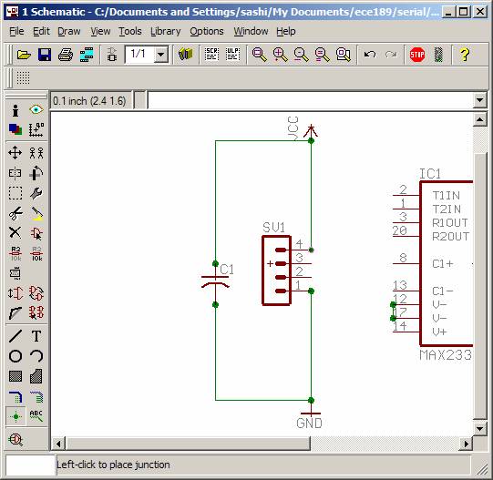
Now we are almost done with the schematic. Just make the rest of the connections as shown. Don’t forget pin 5 on the serial port to ground.